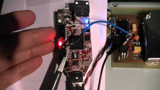
I’ve replaced the local oscillator with a Spartan-6 FPGA and scanning with it’s internal PLL.
I show VGA output, IQ processing, 256 point FFT and audio from one bin. The final details will be published with the next Element14 video about communication…
Video Rating: 4 / 5

Look out, Jeri’s listening to Rush… Limbaugh, that is. 😉
the Sidebands are the HD Radio Feed.
Are you using the Xilinx free FFT core in WebPack ISE?
@ChrisGammell Even HAMs won’t listen to AM. CW/SSB all the way.
@scottrharris Sure. That would work just fine.
Wow! You really want to replace hole PC and use one FPGA 🙂 What to say …
you rulez! Maybe you just need an little tweaking in analog part (I/Q
demodulator + OP) to improve noise figure.
@JeriEllsworthJabber would be cool if you can build a decoder for the HD
Sidebands , love this project, very simular to Flex Radio or SDR-IQ Radios
used by many amateur radio operators.
@mikikg Most of my analog design is driven from the fact I have to use
small single sided boards. I could do a better layout if I had a layer to
route power.
pretty cool Jeri! Fun to watch ur progress.
Great work!
@ki4swy Yeah. I doubt anyone is transmitting stereo AM anymore.
@jeriellsworth Cool. I was reading up on it last night (along with
investigating DCM stuff. It seems like you could generate the quadrature
signals there instead of using 4 times the LO and then doing the two D
flip-flop quadrature shuffle). Hoping to get one going on the Xula-200 I
won in the 555 contest.
@JeriEllsworthJabber I prefer psk32 on a waterfall myself.. Eww CW ?
@mikikg I still don’t have a filter on the front end, so that’s
contributing to the noise. The noise is not a concern of mine now.
Finally I can understand how a chip is really made by watching your videos.
People always say that making a ASIC is a million dollar project. Is that
true? If you are employed by a chip making company and have the tools at
hand, how expensive is it really?
@JeriEllsworthJabber @ChrisGammell Actually – there is a entire community
within the ham ranks that still love and exclusively fiddle with AM
(ancient modulation). They love the nostalgic sound and wider modulation
BW…
Sounds like the aliens from Independence Day.
What kind of FFT algorithm are you using?
@AntiProtonBoy It’s the smallest butterfly architecture that Xilinx offers.
It takes quite a few passes to calculate to result. I think it was ~40-50
clocks.
Amazing!!!
@pikuorguk Almost. I think it was Rush Limbah on that station.
Tube Based GDO,FTW!
@jeriellsworth Absolutely understand Your goals, just keep on going …
this was a side notes … I’m working on similar SDR project but my goals
is to get maximum SNR and dynamic range out of analog part. Once again, you
did a great job!
@scottrharris I am using the free FFT core. It’s configured to be burst
oriented. I tried the streaming configuration, but it took up too much dsp
resources in the tiny FPGA.
@bkraz333 Thanks. I’d suggest getting one of the simple boards like the
Papillio or Terrasic
@hazydave It has termination. 🙂
@whydontyoublogabouti Yes. The scope probe is grounded a mile away from the
signal source. 🙂
@hazydave This is a direct conversion reciever, so I’m using a 4x square
wave to drive a 4066. Check out the Tayloe detectors.
@hazydave Is a low pass filtered LO necessary, since it’s a digital mixer?
The square wave generated by the FPGA should actually be pretty clean, but
it looks worse on the oscilloscope than it is because of the huge loop area
(have a look where the CRO probe’s ground is clipped)
Your progress vs time on this just amazes me. Great work! Will you be using
a reference design for the DSP or doing your own? Also how are you planning
to control and configure the device when disconnected from the PC?
I must be a NOOB. I would love to understand exactly what the practicality
of what Jeri is doing. Jeri, maybe a show of what the reason is for doing
this to the thing-ama-bob you are creating. THANKS!
I love your soldering…
@CurtisStephenson The device will configure from the built in flash. I’m
not sure what the user interface will look like. I may not put much effort
into that at first. (few buttons)
@karmicthreat I’m doing it because it’s a neat circuit. ADC are very
expensive if you want something in 50mhz or more range.
The simple boards will avoid all the time and confusion of built in
peripherals that need to be held in a stable state when you are not using
them.
Are you using a Tayloe because it cheap rather than just doing direct
sampling with a faster ADC?
wow! you are awesome… there is not many ladies out there that like play
with electronics and hardware, I fell very identified with part of your
story, digging into toys and electronics, I used to similar things.. but
less lucky than you.. where I born and I came I did not have electricity at
my home until I have 14, no television, only very old Russian radios that I
use to take apart.
@CurtisStephenson Oh. I might use some IP for the filters.
@300000hp I think the max will be 100mhz local osc (25mhz band)
We’re gonna turn you into ham yet! Looks great Jeri! Can’t wait to see what
you do with filtering and demod in the FPGA.
nice job! what would be the maximum scanning frequency for this radio? and
do you planning to make some finished board or you just playing around with
this stuff?
Nice work! good old Spartan-6 FPGA!!!!