CYBER PEOPLE – Digital Signal Processor (1988)
Video Rating: 4 / 5
High Level Explanation of Digital Signal Processors (DSPs)
CYBER PEOPLE – Digital Signal Processor (1988)
Video Rating: 4 / 5
High Level Explanation of Digital Signal Processors (DSPs)
ham radio video showing cross band rpt with 71a and f6a kenwood rigs
Video Rating: 4 / 5
A few nice APRS images I found:
aprs-1
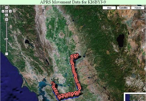
Image by aaron_anderer
work to home, to sac
aprs terminal
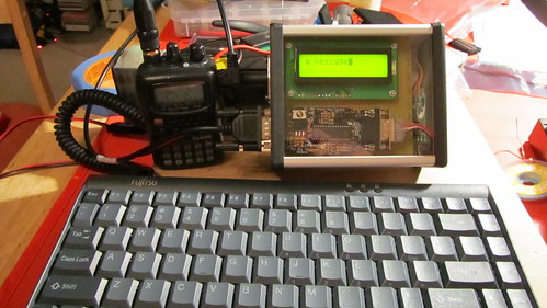
Image by mpechner
aprs terminal
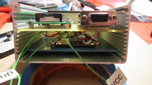
Image by mpechner
Showing the 2 boards in the case.
Demography
By 1968 John Brunner, a British novelist, observed that the earth's people—by then 3.5 billion—would have required the Isle of Man, 572 square kilometres in the Irish Sea, for its standing room. Brunner forecast that by 2010 the world's population …
Read more on The Economist
You are the one percent.
As the first part of that wave starts to retire, draw down their savings and require more healthcare they start to place pressure on social insurance. The dependency ratio starts to change; fewer people of working age support more people who do not. …
Read more on Scholars and Rogues
Canon EOS-1D X Digital SLR camera
Canon's EOS Digital SLR cameras and Canon EOS accessories have a long-standing legacy of providing high-quality results to professionals in a wide range of markets, including sports, nature, cinematography, wedding and commercial photo studios. …
Read more on LetsGoDigital

List Price: $ 15.95
Price: [wpramaprice asin=”0872599213″]
[wpramareviews asin=”0872599213″]
Price: [wpramaprice asin=”B000VNY0FW”]
[wpramareviews asin=”B000VNY0FW”]
More RTTY Products
On this video we talk about the final modifications my good friend Colhane or Mac has done to my Ontario Pilots Survival Knife to improve its bushcraft performance. Those modifications include grounding off the upper hand guard to allow me to choke on the blade, for instance, and the reprofile of its blade into the convex edge. That gives me a sharp and easy-sharpening tool yet with enough metal on the blade to take harder punches such as havier batonning, which cant be done using the Scandi-grind without the risk of damaging it. I owe it all to my friend Mac, who knows A LOT about cutelary and sharpening, re-profiling blades and metal tools! It´s really great to have the chance and the privilege to (finally!!) learn from such a skillful man how to put a good descent edge on my blades, a basic, crucial bushcraft skill yet a very difficult one to be acquiered by many bushcrafters and outdoor people out there (me included!)!
Video Rating: 5 / 5
Furuno FS1503EM SSB-HF Radio is available at PSICOMPANY.COM. Call 1.800.826.2907 More Information on Furuno FS1503EM SSB-HF Radio: www.psicompany.com Furuno FS1503EM SSB-HF Radio provides Continuous Duty and Reliability: The latest addition to Furuno’s HF Radio line that has won the prestigious NMEA award for SSB/GMDSS for the past two years in a row, the FS1503EM is a 150 Watt, PP Single Sideband (SSB) Radiotelephone. This rugged, splash-proof 150 Watt (max) radio is ideal for commercial fishing operations, extended cruising or any situation requiring long-range communication capabilities. The FS1503EM is 100% Sail-Mail/E-Mail compatible right out of the box, and is capable of full Marine HF Weather Fax reception. Furuno FS1503EM SSB-HF Radio has FCC Type Acceptance: The FCC type-approved Furuno FS1503EM SSB-HF Radio incorporates the most advanced technology available and is built to withstand demanding marine conditions. It’s also simple to use, thanks to a choice of rotary control or touchkey frequency/channel selection. Instant access to international calling, and distress frequency 2182kHz is available at the touch of a single button. See us at: www.psicompany.com
Video Rating: 0 / 5

Having a Marine radio can be critical when operating a boat on any type of water. There are many uses for a Marine radio, but the most important is to send a distress signal — here’s how to do it. To complete this how-to, you will need: Boat Marine radio Nautical chart General information about your boat and passengers Call sign and registration number (optional) Compass (optional) Step 1: Call distress signal Tune your marine radio to channel 16 and call out the word “mayday” three times in a row. This is the international hailing and distress frequency. Collect as much information as you can about your vessel, your condition, and your location before making a distress call. Step 2: Name your vessel Call out the name of your vessel by saying “This is” and then repeating the name of your vessel three times in a row. Call out your call sign and registration number once each if you know them. Step 3: Repeat mayday and name Repeat “mayday” and the name of the vessel once more. Step 4: Give position Give the position of your vessel finding your latitude and longitude on a nautical chart, and approximate distance to a known landmark or island. Give your bearing information by describing the direction you’re heading using your compass. Step 5: Describe your condition Describe the nature of your distress by saying something like, “struck a submerged object,” “taking on water,” or “fire on board.” Step 6: Describe what you need Describe any specific assistance you might need …
Video Rating: 0 / 5
List Price: $ 49.98
Price: [wpramaprice asin=”0872597741″]
[wpramareviews asin=”0872597741″]
[wprebay kw=”aprs” num=”0″ ebcat=”-1″] [wprebay kw=”aprs” num=”1″ ebcat=”-1″]
hamradioireland.blogspot.com This is a short film made by Tony Flynn about amateur radio in Ireland, featuring Thos Caffrey EI2JD and Anthony Murphy EI2KC, filmed at Thos’s QTH in Clogherhead.
Video Rating: 5 / 5
Price: [wpramaprice asin=”1859972233″]
[wpramareviews asin=”1859972233″]

Rolando McClain RC – Oakland Raiders (RC – Rookie Card) 2010 Score Football Card – NFL Trading Card in Screwdown Case
List Price: $ 2.95
Price: [wpramaprice asin=”B003VCX4TI”]
[wpramareviews asin=”B003VCX4TI”]
[wprebay kw=”afsk” num=”4″ ebcat=”-1″] [wprebay kw=”afsk” num=”5″ ebcat=”-1″]
開創量測系統新價值 無線/接線式整合系統崛起
目前所使用的多款接線式量測系統,均部署極為精確的時基(Timebase)、鎖相迴路(PLL)電路,與阻抗匹配(Impedance-matched)的訊號路徑。若單以原則來看,接線式系統可符合同步化作業的嚴苛需求。然而,接線式網路與無線網路卻可分別透過IEEE 1588與GPS技術,讓使用者在標準與 …
Read more on 新電子

Welcome to the world of QRP! Now you can explore the excitement of low-power radio operating with this third edition of ARRL s Low Power Communication:
Equipment and Station Accessories – commercial gear, kit-building and home-brew
Antennas wire beams, loops, dipoles, portable antennas and more
Operating Strategies operating techniques, awards, and contesting
NEW! Emergency Communication training, planning and other factors
NEW! Surplus Military Equipment –
List Price: $ 19.95
Price: [wpramaprice asin=”0872591042″]
[wpramareviews asin=”0872591042″]

Upgrade to General and enjoy the thrill of high-power communications on all HF bands!
ARRL’s General Q & A is your authoritative guide to every question in the General Class question pool–everything you need to pass your General Class Amateur Radio license exam! Using ARRL’s General Q & A is the best way to review for the exam with confidence.Upgrade to General and enjoy the thrill of high-power communications on all HF bands!
ARRL’s General Q & A is your authoritative guide
List Price: $ 9.99
Price: [wpramaprice asin=”B005F0GPYU”]
[wpramareviews asin=”B005F0GPYU”]
[wprebay kw=”arrl” num=”8″ ebcat=”-1″] [wprebay kw=”arrl” num=”9″ ebcat=”-1″]
Lecture Series on Communication Engineering by Prof.Surendra Prasad, Department of Electrical Engineering ,IIT Delhi. For more details on NPTEL visit nptel.iitm.ac.in
Single side band with my Degen de-1103
Video Rating: 5 / 5
A few nice Antenna impedance images I found:
Receiving marine weather fax transmission

Image by Richard Corfield (M0RJC)
Price: [wpramaprice asin=”B0006C0FG6″]
[wpramareviews asin=”B0006C0FG6″]

List Price: $ 79.87
Price: [wpramaprice asin=”1900445034″]
[wpramareviews asin=”1900445034″]
Some cool ARRL images:
Split Rock ARA Field Day 2007
Image by bigtowers20
Split Rock Amateur Radio Association ARRL Field Day 2007
Horseshoe Lake, Roxbury Township, NJ
Split Rock ARA Field Day 2007
Image by bigtowers20
Split Rock Amateur Radio Association ARRL Field Day 2007
Horseshoe Lake, Roxbury Township, NJ
Split Rock ARA Field Day 2007

Image by bigtowers20
Split Rock Amateur Radio Association ARRL Field Day 2007
Horseshoe Lake, Roxbury Township, NJ
forums.bsodtv.org
Video Rating: 5 / 5
AR Newsline Report 1785 — Oct. 26 2011:
For the Amateur Radio Newsline, I'm Norm Seeley, KI7UP, in Scottsdale, Arizona. As we go to air, close to 500 aftershocks have been recorded in the area since the earthquake. More amateur radio emergency communications information will be posted on the …
Read more on eHam.net
Ham Radio hams it up Oct. 15
Operating this year from the Emergency Operations Centre for Halton Region and the North Halton Red Cross in Milton, Ham radio operators from the radio groups in Halton region, including the Oakville Amateur Radio Emergency Service and Halton Region …
Read more on InsideHalton.com
www.ece.utah.edu/~ece3300
Video Rating: 5 / 5
This is a professional watch and it is important to note that it is not designed for leisure use. The built in micro transmitter broadcasts on the 121.5 MHz aircraft emergency frequency. If a pilot is to crash land an airplane, he is able to activate the micro transmitter which will alert search and rescue. The micro transmitter is activated by removing a cap on the watch which releases an antenna. The distress frequency has a range of approximately 100 miles and transmits on the frequency that is monitored by Cospas-Sarsat, an international search-and-rescue operation. The rescue signal will remain operational for 48 hours.
Micro- and millimetre-wave signal measurement tools and best practices – Part 2
Their materials, structures and geometries are specially designed for a specific operating frequency range, to yield consistent impedance and reduce signal loss. Avoid compromising the performance of an expensive test system with poor quality or …
Read more on Dataweek (press release)
A Tech's Guide to Component Design Factors in AM RF Gear
In the absence of design limits, if parameters (ie, antenna impedance, etc.) are estimated or uncertain, higher design factors are often applied, as a matter of engineering judgment. On the other hand, lower safety factors may be justified by a …
Read more on Radio World
Cowon D3 Plenue Review
Volume levels on the D3 go loud enough to power pretty much every phone below 100 Ohm impedance properly. The D3 is a bit quieter than other Cowon players, but it is still efficient enough. However, if your D3 comes with a volume-limited EU firmware …
Read more on Anything But iPod
Check out these Amateur Radio Emergency Service images:
Antenna onna Bucket

Image by OpalMirror
Here’s the omni vertical antenna for our CARES radio station at the Firehouse, hoisted to 27 feet above the ground on Mike’s bucket truck.
Tonight’s training session…
Image by kf6gpe
Another good turnout for the local Amateur Radio Emergency Service group.
Here’s a few clips of how things sound on our side of the pile-up – and these are by no means the biggest! Operators in order of appearance are: M0VFC, M0BLF, G4EAG, M0TOC and M1BXF, who along with Martin, G3ZAY (who I didn’t manage to record yet…) formed the Cambridge University WIreless Society DX’pedition to Miquelon in September 2011.
Video Rating: 5 / 5
A rare video of 1989 DXPedition on Ceva-I-Ra Island (Conway Reef). This DXPedition took place on July 1989 with Baldur DJ6SI, Heinrich DJ6JC(SK), Karl DK2WV, Vince K5VT and SWL Frank.
Video Rating: 4 / 5
Some cool APRS images:
aprs_dot_fi-N6ACA-9_track_12Sep2010
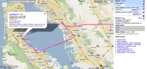
Image by aaron_anderer
An APRS track as seen by the aprs.fi APRS server. My station, N6ACA-9 is running on an old Alinco 2M HT and a Byonics TinyTrak 4 unit using a Duleo GPS. This provides 5 watts into a generic 2 meter magnetic mount antenna.
bread Board Dick Tracy APRS receiver
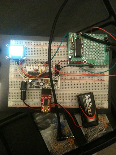
Image by mpechner
This is a proof of concept for the dick tracy aprs receiver.
All the basics work. Now waiting on the small parts so I can fit it all on a wristband 3 inches wide.
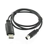
Supports: Windows 2000, Windows XP (All), Windows Server 2003, Windows Vista (All) , Windows Server 2008, Windows 7 (All), Windows Server 2008 R2, Linux and Mac OS X. Link provided to download drivers from FTDI website. No programming software included. Works with Yaesu: FT-100, FT-817, FT-857, FT-897, FT-100D, FT-817ND, FT-857D, and FT-897D.
FTDI Chipset, Manufacturer Technical Support and Warranty Coverage – Due to counterfeit copies of Valley Enterprises interface/programming cables being of
List Price: $ 27.77
Price: [wpramaprice asin=”B0041LNISK”]
[wpramareviews asin=”B0041LNISK”]
Some cool AMSAT images:
ARISSat-1 SSTV
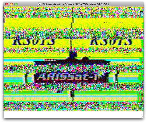
Image by michaelstyne
Captured 8/4/2011 during 12PM UTC pass
Dish slices
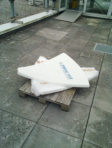
Image by csete
The Alpha Spid rotator
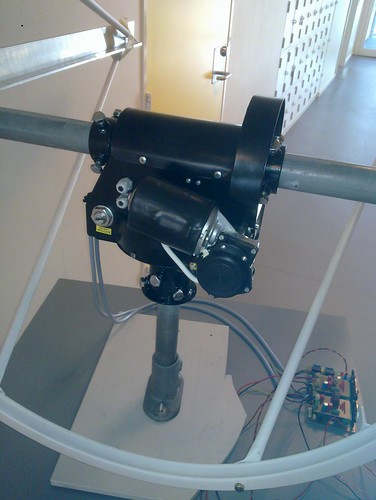
Image by csete
Louisville's long-silent 1450 is back, as all-sports "Buzz"
In March 2010, Cumulus told the FCC that WQKC had transmitter problems and was operating at just 150 watts due to “high-voltage standing wave ratio.” By last November, it told the FCC it had “made a business decision to take the station off the air. …
Read more on Radio-Info.com
Nordic Banks Offer 'Best Place to Hide' From Capital Stress
Oct. 21 (Bloomberg) — Nordic banks may offer investors the best protection against a recapitalization wave that threatens to dilute the share values of Europe's lenders, said UBS AG. “It is a very attractive place for European investors to hide from …
Read more on BusinessWeek
Video Rating: 0 / 5
This is the captured Video from the RFI at Intelsat 1002 XP71.
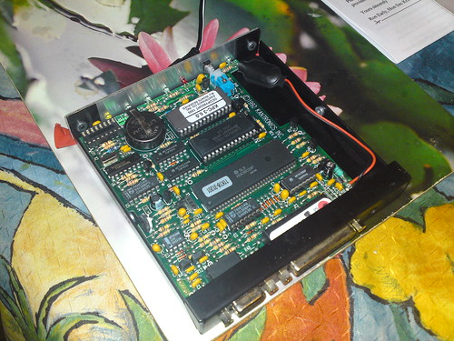
Some cool APRS images:
HX-1 APRS unit

Image by 3D King
The heart of the (radio) unit
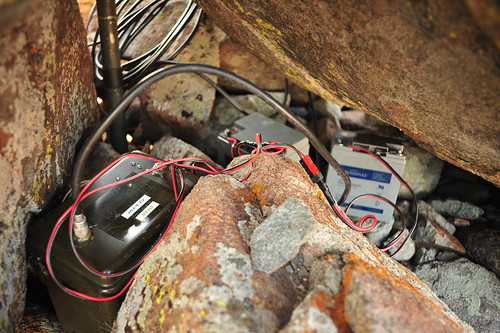
APRS Tracker
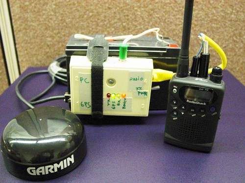
Image by petehoffswell
APRS Tracker, with GPS receiver, transmitter, and power supply. This was originaly created to ride in a drift bouy.
aprs_dot_fi-N6ACA-9_track_22Aug2010
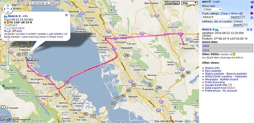
Image by aaron_anderer
An APRS track as seen by the aprs.fi APRS server. My station, N6ACA-9 is running on an old Alinco 2M HT and a Byonics TinyTrak 4 unit using a Duleo GPS. This provides 5 watts into a generic 2 meter magnetic mount antenna.
The characteristic Breitling watch is much larger than the standard face, in part to display the many functions available on most of them. The large face provides better visibility, of course but it is obvious that most of these functions would not be used in day-to-day living conditions. The watch itself has become a luxury status symbol and is widely copied and marketed in the replica market. The primary intent in the production of the watch was as a tool used by aviators. These watches contain features, which might prove helpful to people in this occupation.
Other models have an automatic winding mechanism, which has no electronic components. Additional features found in many Breitling watches are a date display, moon phase, split second and the flyback function.
The manufacturing of all Breitling watches is done in the city of La Chaux-de-Fonds where so many other products related to Swiss watches are produced. Breitling’s history goes back to 1884, but the product most associated with the Breitling is more properly classified as a wristwatch chronograph. The instrument was popular with pilots from the beginning. By 1936, Breitling was named the official supplier for the Royal Air Force. The Chronomat, produced in 1942 contained a circular slide rule.
]]>
The expansion of the brand to the U.S. military and the creation of the Navitimer in 1954 containing the first navigation computer made the watch the hands on favorite by pilots from that time forward. Astronaut Scott Carpenter was wearing a Breitling Cosmonaught chronograph during his Aurora 7 orbital flight. 1969 saw the introduction by Breitling of the world’s first self-winding chronograph, which revolutionized the entire Swiss watch industry. In 1984 Breitling reintroduced the Chronomat, which became Breitling’s best selling model, a position it retains today. Another popular model, the Aerospace was launched in 1985.
The Breitling Emergency version has been credited with the life saving feature of a radio transmitter broadcasting on the distress frequency of 121.5 MHz. This feature can be used as a ELT-type beacon. For military use, the Breitling can be equipped with a transmitter which broadcasts on the military frequency. After 2009, the Satellite system will no longer the frequency, although the signal was never strong enough to receive signals from the miniaturized transmitter.
Two British pilots activated their Breitling Emergency watches transmitters after their helicopter crashed in Antarctic waters. They were successfully rescued by pilots homing in on their transmitter signals.
Those who do not hold a pilot’s license can own the Breitling Emergency only by signing an agreement which states they will bear all costs of a rescue mission should their emergency beacon be accidentally triggered.
Breitling manufactures both quartz models such as the Aeromarine Colt and mechanical steel cased models such as the Breitling Bentley Motors model featuring a 38 jewel self-winding movement which is priced at over 00. There are also Breitling models in titanium and gold, although they are somewhat less expensive than those with the self-winding movement.
Johnny Bender owns and operates WatchesWell.com, an e-commerce website providing quality replica watches of brands such as Cartier, Omega, Gucci, Tag Heuer, and Breitling replica watches.
Find More Distress Frequency Articles
DX News — ARRL DX Bulletin #40:
Activity will be on the HF bands using CW, SSB and PSK31. QSL via bureau. REUNION, FR. Willi, DJ7RJ will be QRV as FR/DJ7RJ from October 4 to 26. Activity will be mainly on the low bands. QSL direct to home call. SCOTLAND, GM. A group of operators will …
Read more on eHam.net
A few nice Antenna tuner images I found:
Inductors and Capacitors
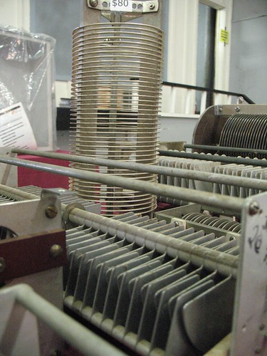
Image by ab9kt
I could make one heck of an antenna tuner!
My first time ever on RTTY or other digital modes. I wish I had a macro lens on the camera and someone else to operate it plus some daylight bulbs. Pimp this video.
Video Rating: 4 / 5
5A7A Libya DXpedition 2006. A total of 112.000 worldwide Amateur Radio contacts. Using all modes including digital modes, EME (Moon Bouncing) and 160m Topband (7700 contacts).
Video Rating: 4 / 5
Michigan Tech Uses Ethernet Radio To Bridge Campus Network
BridgeWave's links have given my team peace of mind that our network won't go down or experience radio frequency interference. We've been able to organize campus IT departments into larger units and, now, services are running out of two main …
Read more on Campus Technology
sIRG, APSCC, ASSI, GVF… Insights Into Interference (Event)
… in several Asian nations, arise from a broader global collaboration of the satellite industry with the World Broadcasting Unions – International Satellite Operations Group (WBU-ISOG) and the Radio Frequency Interference – End User Initiative. …
Read more on SatNews Publishers
Agilent NVNA and X-Parameter Simulation in Advanced Design System. For more information: www.agilent.com For a free evaluation copy of ADS: www.agilent.com
Check out these Standing Wave Ratio images:
G0FAH Dipole SWR Frequency Plot
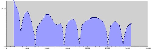
Image by OpalMirror
This is the standing wave ratio (SWR) plot for my G0FAH style antenna (from the ARRL Classic Wire Antennas volume 2 article ‘5 Bands No Tuner’). I measured it using an MFJ-259B Antenna Analyzer I borrowed from a friend, which saved a lot of time in sampling all the data. Yes, I spun a knob and captured each datum plotted by hand.
For the less technical, here’s what’s happening. A transmitter shoves power (measured in Watts) into a transmission line to the antenna. This is called ‘forward power’. Some power eventually gets to the antenna and radiates into space (this is ‘radiated power’). Some of the power bounces back at the transmitter (‘reverse power’). Finally some of it heats up the transmission line (‘heat’). Power bouncing back is not only harmful to the transmitter (high voltages, mostly), it also results in more heating in the transmission line as the waves reflect back and forth (that’s bad). An ideal SWR is 1:1, and anything over 2:1 is increasingly bad news (the vertical axis on the plot shows the first SWR number, basically the higher the more reverse power, so ‘low points’ are good!).
How to reduce SWR? SWR depends in part on antenna and transmission line materials (copper wire, plastic window material, coaxial cable, insulators). More importantly, adjusting antenna and transmission line geometry (length, layout) affects the SWR. You can tweak the lengths until the low SWR spots match up with the frequencies that you care about.
Finally, an antenna tuner is a box with adjustable coils and capacitors inline and shunted to ground, and this helps match an antenna with too much capacitance or inductance so it doesn’t present high voltages and currents to the transmitter itself… the line heats up still but the transmitter doesn’t get cooked.
SWR Frequency Plot – Diamond X-30A
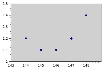
Image by OpalMirror
This is a Standing Wave Ratio plot vs. frequency for a Diamond X-30A VHF/UHF dualband antenna that I have 35′ off the ground at my home operating location, tested with an MFJ-259B. Not surprisingly, it looks just like the specifications.
I’m already using this antenna frequently for local simplex nets (a net is an on-the-radio meeting), one-on-one chats with hams on the go, the South Clackamas County ARES group, the Molalla Amateur Radio Club, as well as talking to hams through any one of the couple dozen local repeaters (local is anything from Salem to Portland to Mt. Hood). It works *much* better than a magmount on the metal roof of the house!
Miracle Antenna w/counterpoise clip
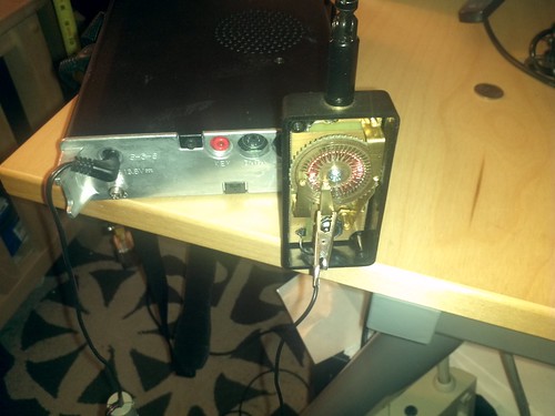
Image by wwward0
I’ve had very little success tuning the Miracle Antenna for 70cm (Ham UHF) operation. The FT-817 complains about high SWR regardless of my efforts to adjust the length for 3/4th wave. However, after clipping a short lead to the shield I’ve been able to get it into "safe" territory with regard to SWR – at least, under the radio’s threshold for the SWR alert. I don’t know what the panel meter is calibrated against, but out of its full range, it’s 4 bars on FM at 5 watts and 3 bars at the lowest power rating. I think there are 8 bars total. Anyway, it’s very touchy.
I left my rubber duck antenna at Resistor and probably won’t have it in hand for a few days, so I was especially interested to get this up and running. The product is sold as UHF friendly, with reasonable performance on UHF (< 2:1 standing wave ratio) so I suspect there is a bit more study required to tune it but otherwise it’s possible to do so.
In the meantime, while it offends my sensibility to do so, I’ll leave the back cover off and use this counterpoise. The rear radio panel has a lug for grounding, but clipping the counterpoise to this or the shield does not help the tuning (or moves it further out in length than I’ve been checking.)
Note that with this tuner, the antenna detent for VHF is very important – it’s the pass-through circuit on the rotor, and is followed by a couple detents which place the wiper over a nonconductive area.
When time permits (and it’s going to be awhile) I’ll work out something more sensible.
KD4ISF
Storfornøyde etter øl-festival
Med hjelp av over 80 frivillige og 1.000 solgte billetter hadde AFSK, med festkomiteen i spissen, virkelig klart å hente den tyske festivalstemningen hjem til Aurskoghallen og fått en ny vri på den gamle hallfesten. – Ølfestivalen er et morsomt …
Read more on Indre Akershus Blad
www.cbradiomagazine.com – This is an overview of the new Alpha 10 Max AM-1000 AM 10 meter export radio. Note: Radio does not have a microphone gain control.. RADIO SPECIFICATIONS TRANSMITTER Power Output AM/FM/CW: 12W SSB: 21W(PEP) Modulation High and low level class B Amplitude Modulation: AM Varied Capacitance Frequency Modulation: FM Inter-modulation Distortion SSB: 3rd order, more than -25dB; 5th order, more than -35dB SSB Carrier Suppression 55dB Unwanted Sideband 50dB Frequency Response AM and FM: 450 to 2500HZ Output Impedance 50ohms, unbalanced RECEIVER Sensitivity SSB: 0.25¼V for 10dB(S+N)/N at greater than 1/2W-audio. AM:1.0¼V for 10 dB(S+N)/N at greater than 1/2W audio. FM: 1.0 ¼V for 20 dB (S+N)/N at greater than 1/2W audio. Selectivity AM/FM:6dB@3KHz,50dB @9KHz SSB: 6 dB@2.1KHz,60dB @3.3KHz Image Rejection More than 65dB IF Freq. AM/FM: 10.695 MHz 1st IF, 455 KHz 2nd IF SSB: 10.695 MHz Adjacent-Channel Rejection 60dB AM/FM &70 dB SSB RF Gain Control 45 dB adjustable for optimum signal reception Automatic Gain Control (AGC) Less than 10 dB change in audio for inputs 10 to 100000 microvolt. Squelch Adjustable; threshold less than 0.5 ¼V. Automatic Squelch Control(only AM/FM) 0.5 ¼V ANL Switchable Noise Blanker RF type, effective on AM/FM and SSB Audio Output Power 4 watts into 8 ohms Frequency Response 300 to 2800 Hz Built-in Speaker 8 ohms, round. 8 ohms. Features: * 6 Band Programmable Frequency Range (28.000 – 30.000 Mhz) * PA – CW – AM – FM – USB – LSB …
Video Rating: 4 / 5

Volkswagen of America, Inc. announced the debut of the new 2012 VW Jetta GLI, which combines the comfort and sophistication of a Jetta with aggressive performance and handling in a sporty yet sleek package. The all-new Jetta GLI is the most differentiated Jetta GLI model ever made by Volkswagen. With a rich heritage that dates back to 1984, the new Jetta GLI is sure to appeal to both automotive enthusiasts and everyday drivers alike. The Volkswagen Jetta GLI offers exceptional features and options, for equally impressive pricing. Available in three trim levels, the Jetta GLI has a starting MSRP of 495. The GLI Autobahn, with an MSRP of 545, adds 18″ alloy wheels, sunroof, dual zone climate control, heated V-Tex Leatherette seats and the Fender® Premium Audio System. The top of the line Jetta GLI Autobahn with Navigation adds the RNS-315 navigation system and keyless access with push-button start technology for an MSRP of 445. The sporty Volkswagen Jetta GLI boasts the award winning 2.0L turbocharged four-cylinder gasoline engine, generating 200 horsepower and a full 207 lb.-ft. of torque at just 1700 rpm, contributing to drivability and response of the vehicle in both everyday and performance situations. The Jetta GLI is offered with a six speed manual transmission as standard equipment. This new model is significantly lighter than the previous Jetta GLI and it offers power and performance coupled with German sensibilities. While EPA figures are not yet available …
Video Rating: 1 / 5
Modem Hamcom

Image by lu6fpj
Pierwsza aktywność SP w ramach programu WZOO
Sponsorem kart QSL za aktywność jest Śląski OT PZK w Katowicach. Nie ma potrzeby wysyłania kart, wszystkie QSO zostaną potwierdzone automatycznie przez biuro, dodatkowo na LOTW. Pasma 80-10m CW, SSB, RTTY – 100W. Przewidywany czas pracy 8-17 czasu …
Read more on Świat Radio
ARI e Scouts per il Jamboree dell'Aria
Intanto, con gli scouts divisi in settori operativi, Angelo it9ccr e Dario it9zzo trasmettevano e ricevevano sia in SSB, sia in digitale (PSK31, RTTY, ecc…), mentre Corrado it9bij e salvo it9clu hanno coordinato le attività in VHF ed echolink. …
Read more on Ondaiblea (Blog)
From around the year 1929 to the late 1960s, large alternating current power systems were modeled and studied on AC network analyzers. These were an outgrowth of the DC calculating boards used in the very earliest power system analysis. These systems were essentially models of the power system, with generators, transmission lines, and loads represented by miniature electrical components with scale values in proportion to the modeled system. Model components were interconnected with flexible cords to represent the schematic of the modelled system. To reduce the size of the model components, the network analzyer was energized at a higher frequency than the 50 Hz or 60 Hz utilityfrequency, and model circuits were energized at relatively low voltages to allow for safe measurement with adequate precision. AC network analyzers were much used for power flow studies, short circuit calculations and studying system stability but were ultimately replaced by numerical solutions running on digital computers. Since the multiple elements of the AC network analyzer formed a powerful analog computer, occasionally problems in physics and chemistry were modelled (by such researchers as Gabriel Kron of General Electric), during the period up to the late 1940s prior to the ready availability of general-purpose digital computers.
One of the most essential pieces of TE in the lab is the network analyzer. It can be used to measure impedance, VSWR, loss, gain, isolation, and group delay of any two ports of a multi-port network (don’t make us draw a potato with arrows here). The two big guys in network analyzers are Agilent, the 800 pound gorilla once known as Hewlett Packard, and Anritsu once known as Wiltron before they turned Japanese.
Network analyzers fall into two categories. Vector analyzers are capable of measuring complex (magnitude and phase) reflection and transmission; scalar analyzers can only measure magnitude.
Scalar network analyzers measure the amplitude portion of scattering or S-parameters, reflection and transmission coefficients between the incident and reflection waves that describe a device’s behavior under linear conditions at the microwave frequency range. Most scalar network analyzers are used to measure transmission gain, transmission loss, return loss, and standing wave ratio (SWR). Traditional devices use diode detectors to convert a radio frequency (RF) input signal to a proportional DC level. This method is less expensive than the tuned-receiver approach, but inherently scalar in nature. Some scalar network analyzers include a 5 ¼” floppy drive or a 3 ½” disc drive. Others include a compact disc (CD) drive for loading programs or storing data. Tape drivers and display options are also available. For example, analog meters display S-parameter values with a simple visual indicator such as a needle. Digital readouts use numeric or application-specific display. With video displays, data is presented via a cathode ray tube (CRT), liquid crystal display (LCD) or multi-line form.
There are several form factors or instrument styles for scalar network analyzers. Portable or benchtop devices can be moved with relative ease and used in a variety of applications. They may include a case or handle, but are not necessarily designed for hand held use. Fixed scalar network analyzers are kept in one location and meant to be used in one place. They are usually stand-alone devices. PC-based or “black box” instruments and modules do not include an integral display, but instead interface to a computer. They typically plug into the backplane or motherboard, or otherwise interface directly with the computer bus. For each form factor or instrument style, operating temperature and operating humidity are important considerations.
Performance specifications for scalar network analyzers include frequency range, frequency accuracy, frequency resolution, output power range, and nominal input impedance. Typically, applications such a wireless communications require higher frequency capabilities. For example, 900 MHz applications require devices with a high frequency of 10 * 900 MHz for a total of 9 GHz. Other applications must be able to measure lower frequency baseband or intermediate frequency (IF) signals. Frequency accuracyis specified as the sum of several sources of errors, including frequency-reference inaccuracy, span error, and resolution bandwidth (RBW) center-frequency error. Frequency resolution is an important specification for applications that measure close signals that need to be distinguished from one another. Output power is the 1-dB compression point that results in a 1 dB decrease in amplifier gain. Nominal input impedance is the amount of load that an input places on the signal source that drives the load. High input impedance is generally desirable and implies that little change in the signal is expected when the circuit is connected. The most common input impedances for scalar network analyzers are 50 and 75 .
There are several interfaces for scalar network analyzers. RS232, RS422, and RS485 are common serial interfaces. Universal serial bus (USB) is a 4-wire, 12-Mbps serial bus for low-to-medium speed connections. IEEE 1394 or FireWire is an interface standard adopted by the Institute of Electrical and Electronics Engineers (IEEE) for very fast digital data transfers. FireWire is a registered trademark of Apple Computer, Inc. The general-purpose interface bus (GPIB) is designed to connect computers, peripherals and laboratory instruments. Small computer systems interface (SCSI) is an intelligent I/O parallel peripheral bus. Transistor-transistor logic (TTL) is a common type of digital circuit in which the output is derived from two transistors. Some scalar network analyzers use parallel channels or Ethernet networks. Others use modems or communicate via radio transmissions or telemetry.
Special types of network analyzers can also cover lower frequency ranges down to 1 Hz. These network analyzers can be used for example for the stability analysis of open loops or for the measurement of audio and ultra sonic components.
]]>
Vector network analyzers
A word about acronyms concerning network analyzers… vector network analyzers (VNAs) are often called “ANAs” by old engineers. ANA stands for “automated network analyzer”. A long time ago during the Carter administration, the original network analyzer (H-P 8409) was not automated, in the sense that TE error correction was done by hand. Return loss measurements could not exceed the VSWR of the equipment, so you couldn’t resolve beyond 20 dB return loss in most cases. Gain and insertion loss and phase were calculated from the subtraction of two measurements (first the through connection, then the DUT connection). It was a bad time to be alive.
Then the first automated network analyzers were introduced. A minicomputer (about equal to a 1000 watt, five dollar calculator) grabbed the vector data from the 8409, and did some fancy manipulations that resulted in automatic error correction and accurate magnitude and phase of the four S-parameters. It was considered magic. The next step was to build the error correction into the test equipment (no external computer) and display the error-corrected measurements in nearly real time (the original HP 8510, circa 1982). Today vector network analyzers are all automated (error correction is built in). And the acronym ANA has stuck.
This type of network analyzer consists of a sweep oscillator (almost always a synthesizer so that measurements will be repeatable), a test set which includes two ports, a control panel, an information display, and an RF cable or two to hook up your DUT. Each port of the test set includes dual directional couplers and a complex ratio measuring device. Other options include a means for bias voltage/current injection, and a computer controller to manipulate and store data. The “classic” vector network analyzer is the Agilent (HP) 8510, shown below. Depending on how much you spend, this analyzer can make measurements from 45 MHz to 110 GHz.
Before you jump into vector network analyzer measurements, you will have to calibrate the network analyzer. There are many types of calibration techniques, and even more types of calibration standards. A typical calibration will move the measurement reference planes to the very ends of the test cables. You will have the choice of calibrating for reflection or transmission only, using either of the two ports or both of them together. For most tasks you will probably calibrate both test ports for reflection and transmission, which will allow you to measure full two-port scattering matrices (S-parameters for your device under test (DUT). This is referred to as “twelve-term error correction”.
Before you perform a calibration, you should do a little “preflight” check-out of the TE and DUT. The following are the guidelines to follow before you proceed with calibiration:
What frequency range do you need to measure?
Does the cal kit, cables and any adapters you need operate over the desired band?
Are the cables in good condition? (Connect them together and see what the effects of gently bending them have on uncalibrated transmission and reflection parameters).
Will the cables reach the DUT? (This seems obvious, but I have seen people waste time calibrating only to discover that the test cables are too short to reach both ports of the DUT).
Guidelines in calibrating a vector network analyzer
The reflection calibration for each port requires three standards, typically: an open circuit, a short circuit, and a matched 50-ohm load (for waveguide calibration, a pair of offset shorts and a load are used. An open in waveguide usually acs closer to a load due to radiation). The matched load can be a “broadband load”, meaning that it has very low reflection coefficient over a lot of bandwidth, or a sliding load. Sliding loads are expensive and fragile standard which should only be used if your measurement requires great accuracy (perhaps you want to be able to tell the difference between a 1.01:1 VSWR and a 1.02:1 VSWR). The sliding load recognizes that a “perfectly matched” 50 ohm calibration standard can never exist, but a series of loads with equal mismatch but varying phase can be used to draw a circle around the center of the Smith chart, thereby solving for the perfect load. My advice to you: unless someone takes the time to show you how to use the sliding load properly and remember to:
The particular set of cal standards (and test cables) that you use will depend on what frequency band you need to cover. Coaxial calibration kits come in type N, 7 mm, 3.5 mm, 2.92 mm, 2.4 mm, and 1.0 mm. There are waveguide calibration kits for every waveguide band. Be sure not to exceed the frequency capability of the test set, cables, adapters and calibration
that Cal kits are expensive, and pieces of the cal kit should NEVER be used as adapters loads in any test set. And always put the little plastic covers onto the calibration pieces, you want to prevent dirt, skin, grease, etc. from degrading the accuracy of future calibrations. To check the validity of your calibration, as well as the general health of the test equipment, you need to look at a few things after you calibrate. If you are doing transmission measurements, check the residual error in a “through” connection (connect the test cables to each other). You should see 0 dB plus or minus 0.05 dB or better. The phase should be very close to 0.0 degrees as well. The return loss of both ports should be at least 40 dB but can be better than 60 dB if you are using good equipment. The transmission and reflection parameters should not vary significantly when you gently bend the test cables, or you have a bad connection. If you see an issue with the calibration you just did, figure out the problem before you perform another calibration, or you will be wasting your time and adding needles wear and tear to the cal kit and test cables.
: During calibration, if you are measuring the loss of some test cables and don’t expect to see transmission data under -20 dB, go ahead and omit the isolation cal standard. But if you want to see the steep skirts of a filter or the reverse isolation of a multi-stage amplifier, you should perform the isolation step.
: This will improve the accuracy of your data, so long as you do it during the calibration as well as the actual measurement. But it will slow down the measurement process noticeably, a consideration if you have a lot of data to collect in limited time.
This is an option on most new network analyzers, reducing IF bandwidth also improves measurement accuracy. Try reducing from 35 kHz down to 500 Hertz.
: Smoothing is cheating. Smoothing reduces the “bumpiness” of a frequency response by averaging data across a couple of frequency points and using the result at one frequency. But if you need to cheat to get some data for the boss who is standing behind you, go for it. The only time that smoothing may actually improve measurement error is in group delay mode (note: this is referred to as the “aperture” setting when you are using Anritsu (Wiltron) equipment. The group delay is actually calculated from the slope of the phase angle versus frequency, and the “aperture” allows the user to define how much frequency band top take the slope over.
: When you use the auto scale, it quickly displays visual information on the parameter you are investigating. But when you actually plot the data on a pen plotter or printer or using an Excel spreadsheet, use a scale that makes sense. Like 2 or 5 or 10 dB per division. NOT 3 or 6 dB per division. If I have to explain why you should do this, you should seriously consider a new career outside of engineering. Also, when you are plotting the same type of data for units of the same type that you are measuring, Try to use the same scale for all of them, or real engineers will consider you a flake when they have to check out your data.
Scalar Network Analyzers
Scalar network analyzers measure the amplitude portion of scattering or S-parameters, reflection and transmission coefficients between the incident and reflection waves that describe a device’s behavior under linear conditions at the microwave frequency range. Most scalar network analyzers are used to measure transmission gain, transmission loss, return loss, and standing wave ratio (SWR). Traditional devices use diode detectors to convert a radio frequency (RF) input signal to a proportional DC level. This method is less expensive than the tuned-receiver approach, but inherently scalar in nature. Some scalar network analyzers include a 5 ¼” floppy drive or a 3 ½” disc drive. Others include a compact disc (CD) drive for loading programs or storing data. Tape drivers and display options are also available. For example, analog meters display S-parameter values with a simple visual indicator such as a needle. Digital readouts use numeric or application-specific display. With video displays, data is presented via a cathode ray tube (CRT), liquid crystal display (LCD) or multi-line form.
There are several form factors or instrument styles for scalar network analyzers. Portable or benchtop devices can be moved with relative ease and used in a variety of applications. They may include a case or handle, but are not necessarily designed for hand held use. Fixed scalar network analyzers are kept in one location and meant to be used in one place. They are usually stand-alone devices. PC-based or “black box” instruments and modules do not include an integral display, but instead interface to a computer. They typically plug into the backplane or motherboard, or otherwise interface directly with the computer bus. For each form factor or instrument style, operating temperature and operating humidity are important considerations.
Performance specifications for scalar network analyzers include frequency range, frequency accuracy, frequency resolution, output power range, and nominal input impedance. Typically, applications such a wireless communications require higher frequency capabilities. For example, 900 MHz applications require devices with a high frequency of 10 * 900 MHz for a total of 9 GHz. Other applications must be able to measure lower frequency baseband or intermediate frequency (IF) signals. Frequency accuracyis specified as the sum of several sources of errors, including frequency-reference inaccuracy, span error, and resolution bandwidth (RBW) center-frequency error. Frequency resolution is an important specification for applications that measure close signals that need to be distinguished from one another. Output power is the 1-dB compression point that results in a 1 dB decrease in amplifier gain. Nominal input impedance is the amount of load that an input places on the signal source that drives the load. High input impedance is generally desirable and implies that little change in the signal is expected when the circuit is connected. The most common input impedances for scalar network analyzers are 50 and 75 .
There are several interfaces for scalar network analyzers. RS232, RS422, and RS485 are common serial interfaces. Universal serial bus (USB) is a 4-wire, 12-Mbps serial bus for low-to-medium speed connections. IEEE 1394 or FireWire is an interface standard adopted by the Institute of Electrical and Electronics Engineers (IEEE) for very fast digital data transfers. FireWire is a registered trademark of Apple Computer, Inc. The general-purpose interface bus (GPIB) is designed to connect computers, peripherals and laboratory instruments. Small computer systems interface (SCSI) is an intelligent I/O parallel peripheral bus. Transistor-transistor logic (TTL) is a common type of digital circuit in which the output is derived from two transistors. Some scalar network analyzers use parallel channels or Ethernet networks. Others use modems or communicate via radio transmissions or telemetry.
Bruce Jordan is the Marketing Specialist of icontestequipment.com, for more details visit
www.icontestequipment.com
This is a good video so many people get the theory wrong.
Video Rating: 5 / 5
Related Standing Wave Ratio Articles
Check out these Cross Band Repeater images:
Firehouse Station
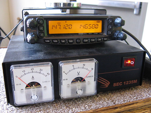
Image by OpalMirror
Mike’s VHF+UHF radio (which is really two radios, and can also do cross-band repeater function – very useful in emergency situations) and a 13.8 VDC power supply allowed him to talk to us down at the Dibble House.
A few nice Yaesu images I found:
Yaesu, Tokyo

Image by forced rhubarb
Yaesu VX-7R Box
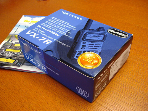
Image by craig1black
A few nice PSK-31 images I found:
The radios
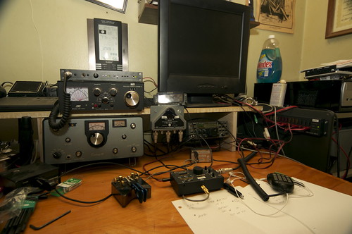
Image by randyrat
This is the right side of the desk – my operating position. All the radios (except the Century 21) are powered with solar. As soon as I figure out how, the Century 21 will be also. The pedastal the power strip is mounted on contains the batteries.
A Realistic DX-100L is made more stable by adding a better heatsink to a transistor in the VFO, and then receives RTTY from DWD Hamburg, and a weather fax from GYA Northwood. users.belgacom.net
Video Rating: 5 / 5
ICPO Bulletin (21-28 October 2011)
[NG3K] 23/10/2011: Members of the Dutch DX-pedition & contestgroup PA6Z are planning a DXpedition from 23 till 30 October 2011 to the isle of Guernsey (IOTA EU-114, WLOTA 0013), using the callsign MU/PA9M. They will be active from 160-6 metre CW and …
Read more on Southgate Amateur Radio Club
Digital Signal Processing techniques improve signal quality or extract important information by removing unwanted part of the signal. The introduction of general purpose microprocessors in the late 1970’s and early 1980’s made it possible for DSP techniques to be used in a much wider range of applications. The microprocessors such as the Intel x86 family were not suitable for the numerically-intensive requirements of digital signal processing, and the increasing importance of DSP led major electronic manufacturers to develop DSP chips, the design of which met all the requirements of digital signal processing.
DSP is a programmable chip and is capable of carrying out millions of floating point operations per second. Typical DSP application fields are audio signal processing, video signal processing, image processing and telecommunications devices. DSP is the basis of many technologies including mobile phones, personal computers, video recorders, CD players, hard disc drive controllers and modems.
The application of digital signal processors in cellular phones is very significant. Signal compression, an important application of digital signal processor, is used in cellular phones to permit a larger number of calls to be handled simultaneously within each local “cell”. The signal compression technology helps to communicate to one another by seeing them while talking. This facility is available with the help of a computer monitor, small video camera and a conventional telephone line linking them together. DSPs can be used in applications that require a high computational speed. Such applications include computer video boards and specialized co-processor boards designed for intensive scientific computation.
Digital signal processors account for a substantial proportion of the world market for electronic devices. And therefore, the leading electronics manufacturers have invested heavily in DSP technology.
A few nice Electro-Magnetic Interference images I found:
Generando poder – Generating power

Image by yvetteSoler
Como siempre, el generador es una torre de cuarzo blanco. Su poder se aumenta con el poder de cuarzo natural, calcedonia y cornalina. Un orgonite los protege de la interferencia electro-magnetica.
The main generator is a clear quartz. Its power is augmented with a natural quartz, chalcedony and carnelian. An orgonite protects it from electro-magnetic interference.
A few nice Backscatter images I found:
Backscatter from Water 2

Image by Caro’s Lines
Backscatter from Water 3

Image by Caro’s Lines
KE7FTE, N7QQU and W9ERT show us the “drag and drop” flexibility of the Icom D-STAR System. Offering reliable exchange of large image files, email, word-processing and other files that emergency responders and served agencies find invaluable.
Stephen Marshall, WW4RX, explains who are MC ARES and what the Amateur Radio Emergency Service serves.
Video Rating: 0 / 5
A few nice ARRL images I found:
Split Rock ARA Field Day 2007
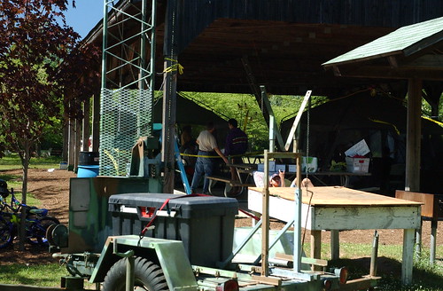
Image by bigtowers20
Split Rock Amateur Radio Association ARRL Field Day 2007
Horseshoe Lake, Roxbury Township, NJ
Split Rock ARA Field Day 2007
Image by bigtowers20
Split Rock Amateur Radio Association ARRL Field Day 2007
Horseshoe Lake, Roxbury Township, NJ
Sony ICF-7600D

Image by Danny McL
My first digitally tuned radio with Short Wave and SSB (Single Side Band) reception too. A superb radio.
PW-Sat to launch in January
The single channel transponder will operate in a similar way to AO-16. The uplink on 145.900 MHz will be FM and the downlink on 435.020 MHz will use the BPSK telemetry beacon transmitter to produce Double Sideband (DSB) that can be received on an SSB …
Read more on Southgate Amateur Radio Club
Under Scrutiny:Genii die young
We would have started from the simple crystal receiver and graduated to much larger projects ranging from a continuous wave transmitter using Morse code to single sideband transmission (SSB). I will never forget the first day we made a contact on the …
Read more on Barbados Advocate
Single in Studio City: Face Your Fears and Find Freedom
When you're at ease enjoying your companionship, others will jump on the band wagon. You'll end up attracting friends and lovers who fancy hanging out with you. By adjusting your perspective, coping with anxieties can be a stimulating. …
Read more on Patch.com
North Texas Balloon Project presents: Texas high altitude balloon flight – This video is a demonstration cross-band repeater downlink on 147.560 MHz. Details on the cross band repeater: Payload: Cross-band Repeater Package Purpose: Short & long-distance amateur-to-amateur radio contacts Summary: Utilize a pair of radios coupled to a miniature repeater controller to allow Amateur Radio licensed operators separated by either short distances (LT 50 miles) or long distances (50-250 miles) to make radio contact through the balloon package Technical Equipment Details: o A pair of Yaesu VX-2R dual-band amateur transceiver – Act together, one as receiver and one as transmitter – Radio power supplied by internal NiMH battery pack – Uplink radio receives on 445.800MHz – Uplink radio modified to provide external Carrier-operated squelch (COS) – Downlink radio transmits on 147.560MHz at ½ watt of output power o A pair of Diamond RH77CA dual-band antennas, one per transceiver o NRHC-micro repeater controller – Provides periodic identification – Controller power supplied by 9VDC alkaline battery More info: www.ntexbp.org http www.edtexas.com (3551, 3552) .
Video Rating: 0 / 5

RX-Down 145.800 fm TX-UP 437.800 fm I managed to get in to the cross band repeater early and worked M0IKB Angus from Scarbourgh E.Yorkshire from Baildon W.Yorkshire via the International space station 300 miles up in space. Lots of other radio hams can also be heard during the ISS pass over my location. I used a Yaesu FT-847, IOIo beam and SATSCAPE. more info at my site via my Youtube Channel. thanks for watching best 73.
Video Rating: 5 / 5
Ham radio operators fill communications void
The group also developed a walking stick antenna, which is used for search and rescue operations to boost the power of radios. Helping others is a large part of the group's motivation, he said. “It's almost like being a Boy Scout for the rest of your …
Read more on Allegan County News
ARNewsline Report 1784 — Oct 21 2011:
Packed in a rainproof canvas box, the HF sets included a short wire antenna that would work using skywave or NVIS propagation. This, to contact any of several radio command posts set up and manned by WICEN of New South Wales. …
Read more on eHam.net
Some cool Radio Frequency Interference images:
RFI testing of Playstation 3 dualshock
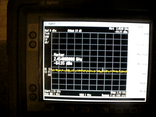
Image by C G-K
I live on a radio observatory that operates within 0.5 – 12.5GHz. Luckily, our house is about 1km from the center of the ATA, but, we still want to limit our RF emissions as much as possible. However, we’d also like to use our new ps3! So, I just borrowed our 0-26GHz spectrum analyzer and mated it with a 2-12GHz horn et voila:
The first part of the video is a bit too dark and it is of me showing the controller plugged into the USB cable, and then turning on the ps3 with the controller. I then put the analyzer into max hold mode to show that there is a bit of bluetooth communications in the first 1-2s of operation, but not afterward.
A) It can see the bluetooth comms in the alloted 2.4-2.481GHz
B) When plugged into USB, the controllers *do not use bluetooth* (WOO!)
C) When first turned on, even with the USB cable plugged in, there’s a small amount of bluetooth comms in the first 1-2 seconds.
D) The horn was about 1ft away from the controller, background (controller off) level when measuring 2.350 – 2.520 was about -61dBm
Da) When turned on, the peak bluetooth signals were -30dBm at 1ft with most being smaller.
Looking Down

Image by Paul L McCord Jr
This is at the 50 foot level looking straight down. This shows my radio frequency interference (RFI) problem with my neighbor’s power and cable lines literally feet from my tower.
Yaesu FT-847 By Paul Corrigan G4JNN. Artistic images of the Yaesu FT-847 All Mode Amateur Radio Transceiver. www.g4jnn.com www.g4jnn.com www.g4jnn.com www.g4jnn.com

Just received my 2012 MFJ Ham Catalog loaded with new toys for the Amateur Radio Hobbyist.
Presenting electromagnetic compatibility concepts in an analytical fashion, this text utilizes basic electromagnetic theory to deduce the design formulae required for effective positioning of components and shielding of cables and cabinets. It discusses unintentional coupling between nearby devices, components on a chasis or printed-wiring card, circuit theory and filed theory, the proper shielding of cables, grounding considerations and shield penetration by conducting wires.
List Price: $ 69.00
Price: [wpramaprice asin=”0134639022″]
[wpramareviews asin=”0134639022″]