Cheap Computer Controlled TV Rotator
for AMSAT Satellites
How would you like to have a complete, cheap computer controlled rotator system for working the current 18 (soon to be at least 20) popular, active ham radio satellites for a total cost of under $350 including antennas, software, interface and rotator – with excellent satellite tracking software and rig control included for free?
Note: Since writing and publishing this page, I no longer have this setup because I “graduated” to the full-blown AMSAT LEO Pack and Yaesu G-5500 rotators. Sometimes, I think my old setup – the system you’re reading about here was nearly as good – but was a LOT less hassle for a LOT less money! When I move next time, I am seriously considering going back to this same setup described below.
Thanks to friend Robin Moseley, G1MHU, I’ve been able to finally and cheaply implement computer control tracking with my equally cheap TV rotor that I use for working the AMSAT satellites.
On top of that, I even ended up with excellent satellite tracking software, as a bonus, that actually works exactly the way it is supposed to, for no extra charge!
I know there are a lot of newbies and even a lot of oldies that might have an interest in getting on the amateur satellites – but who have been turned off by the high cost of a computer controlled antenna system. This approach might be a game changer for those with limited dollars who still want to work the birds without spending $2,000 or more on the antenna system.
Photo Slide Show: Cheap Computer Controlled TV Rotator for AMSAT Satellites – Hope These Help Answer Some Questions!


Did I Mention Cheap?
You may notice the above preponderance of the word “cheap.” If you’re like me, you have so many interests that you end up with limited resources by the time you try to buy all of the necessary toys for each interest.
Ham radio has been one of my primary hobbies since I was 14 years old and probably my most enjoyable hobby that I do without my wife. Since my wife has zero interest in ham radio, for some reason, she seems to prefer that we allocate more resources toward those things that she and I do together. Go figure.
Then and Now – My Ham Radio Satellite Setup
Over two dozen years ago I had a full set up for working the ham radio satellites including big circularly polarized beams, mast mounted preamps and a Yaesu G 5400 AZ EL rotor.
Now as I get back into this aspect of the hobby, I am on a tighter, semi-retired budget and didn’t want to spend $1,000 for another computer controlled Yaesu rotor system to move around less than 10 pounds of antenna.
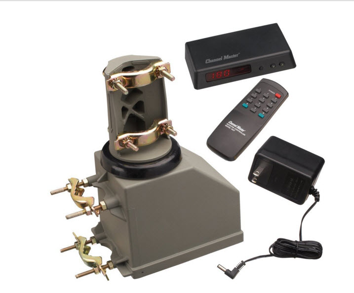
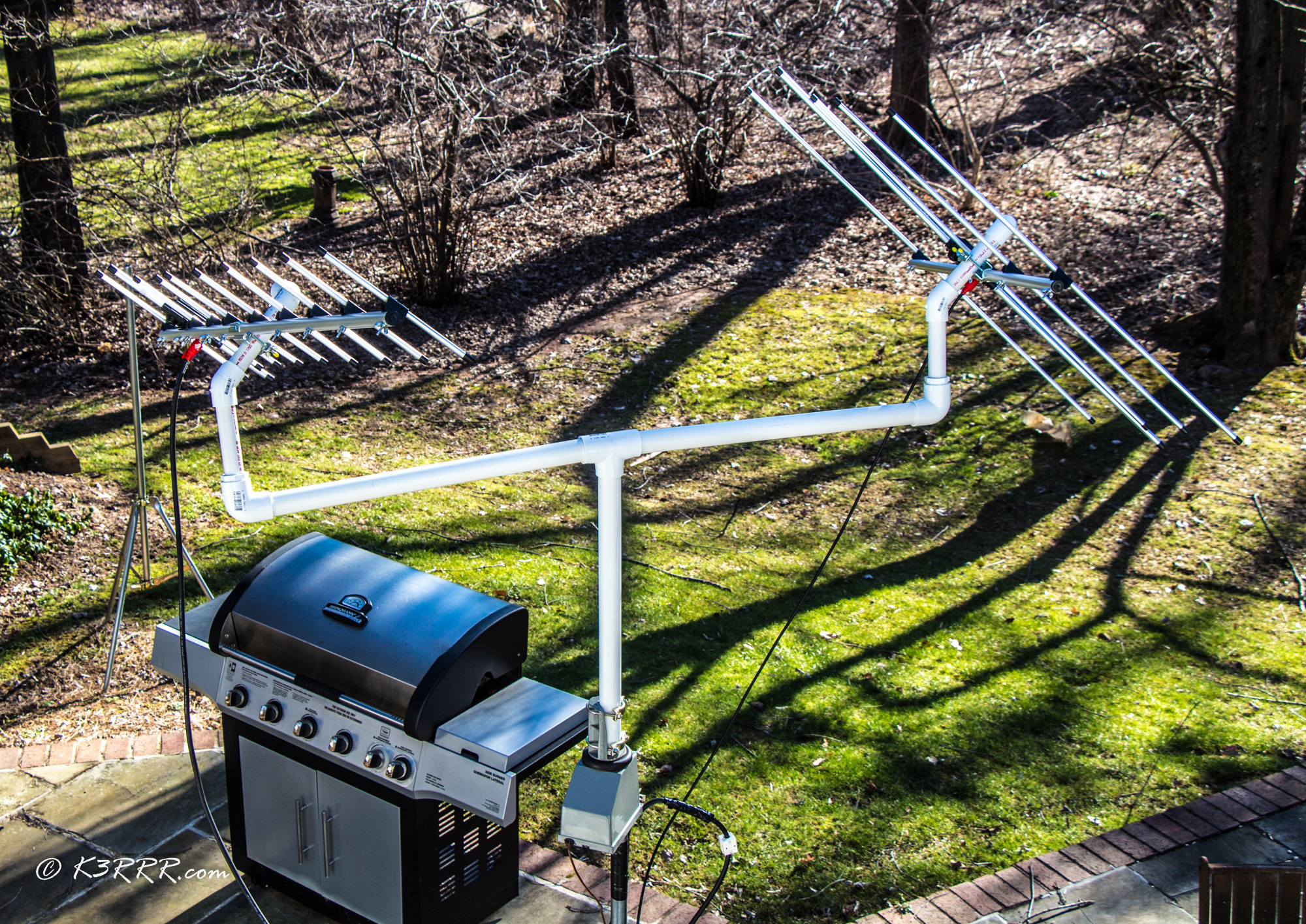
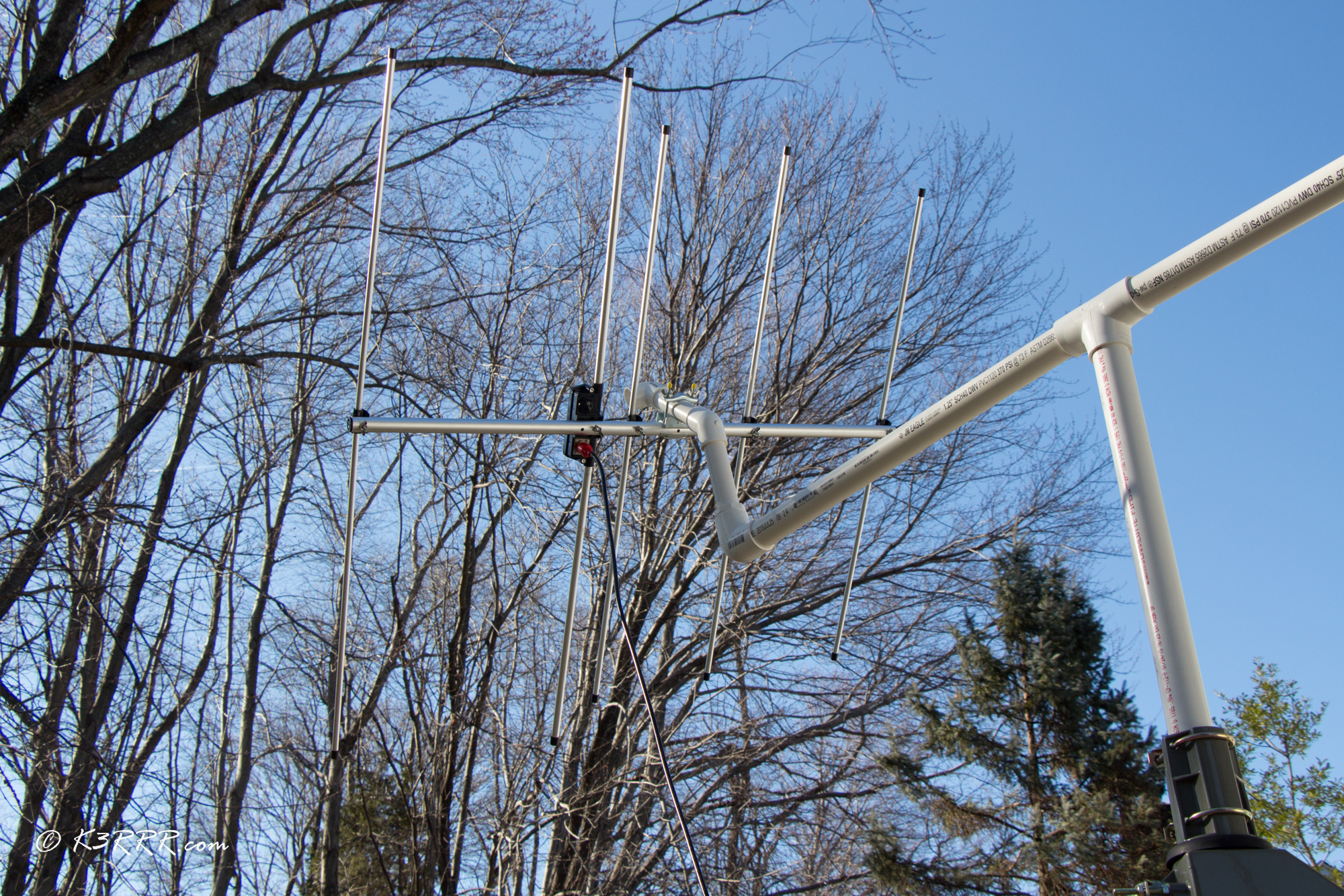
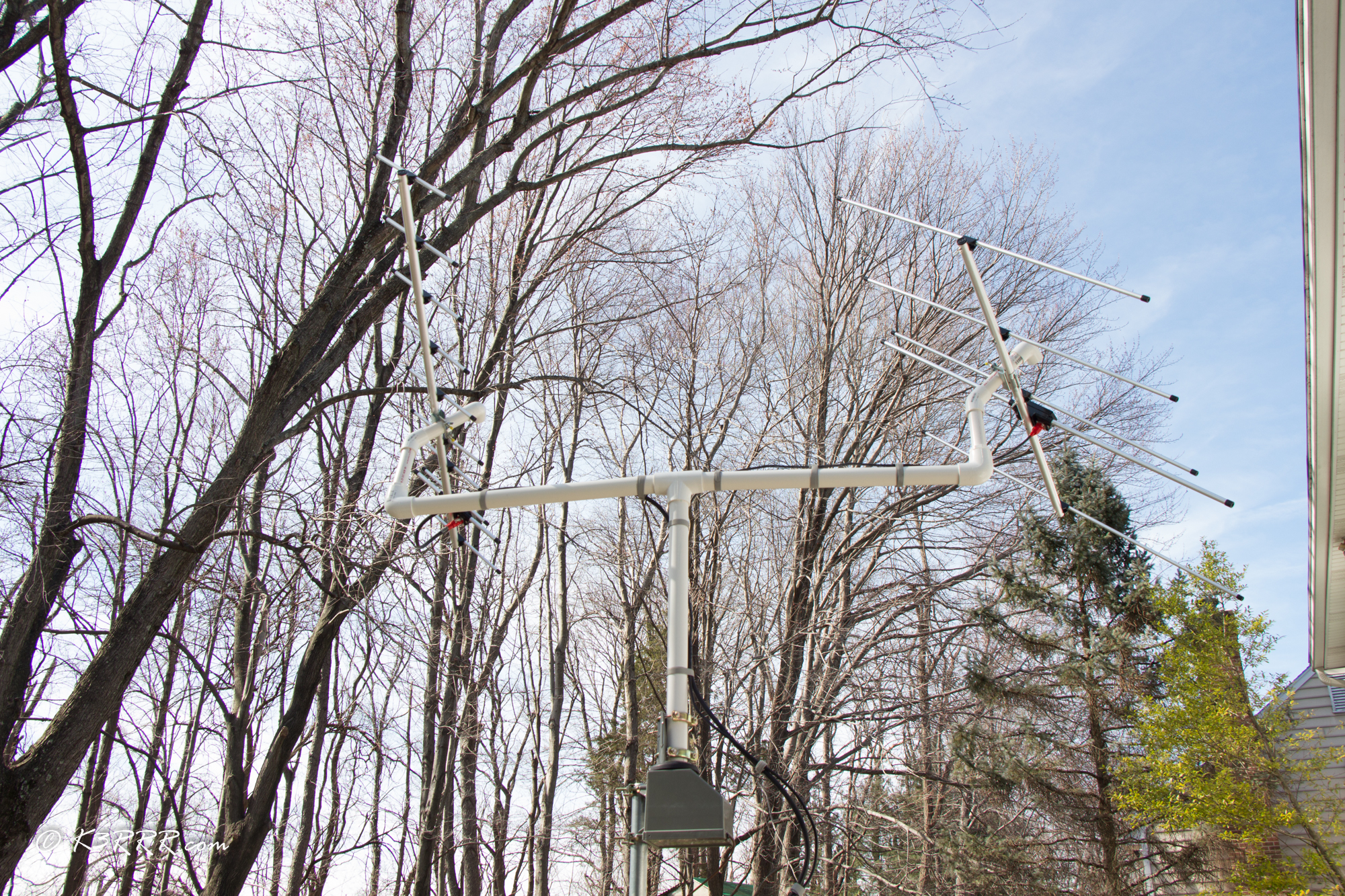
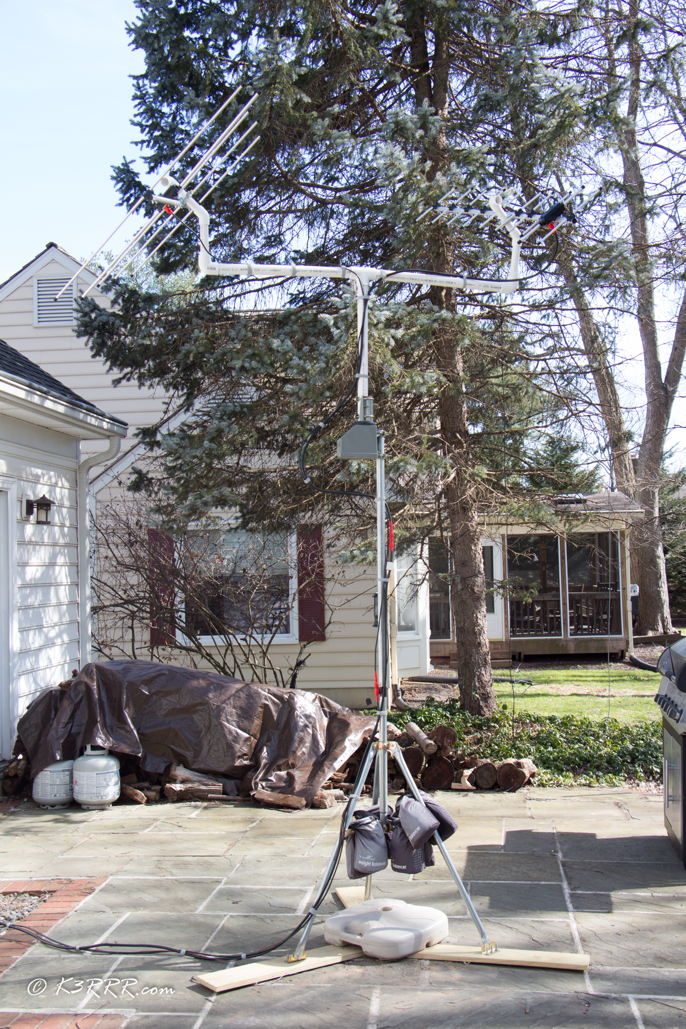
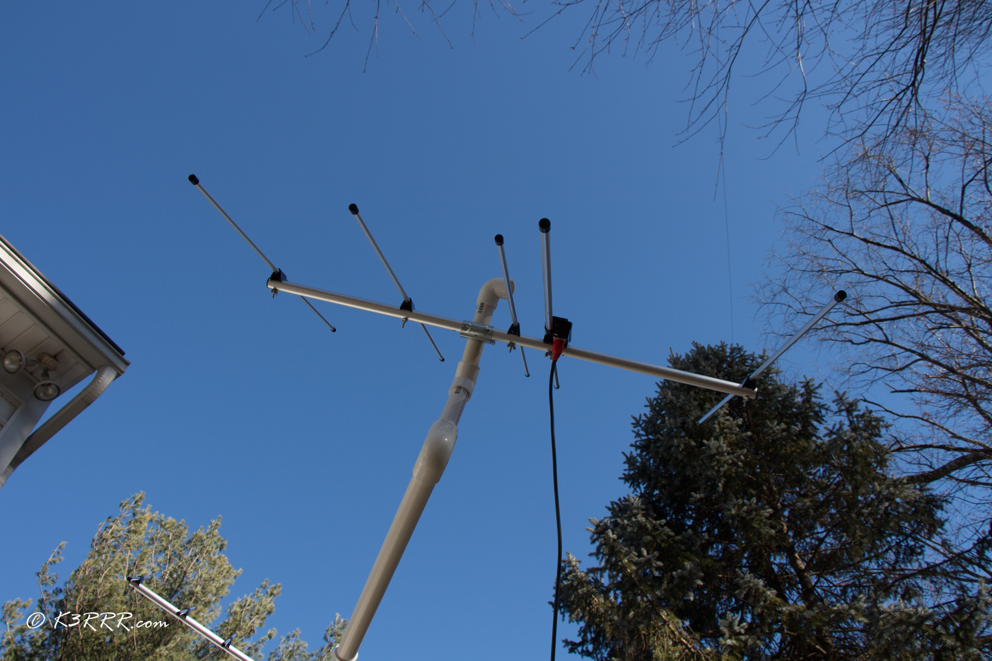
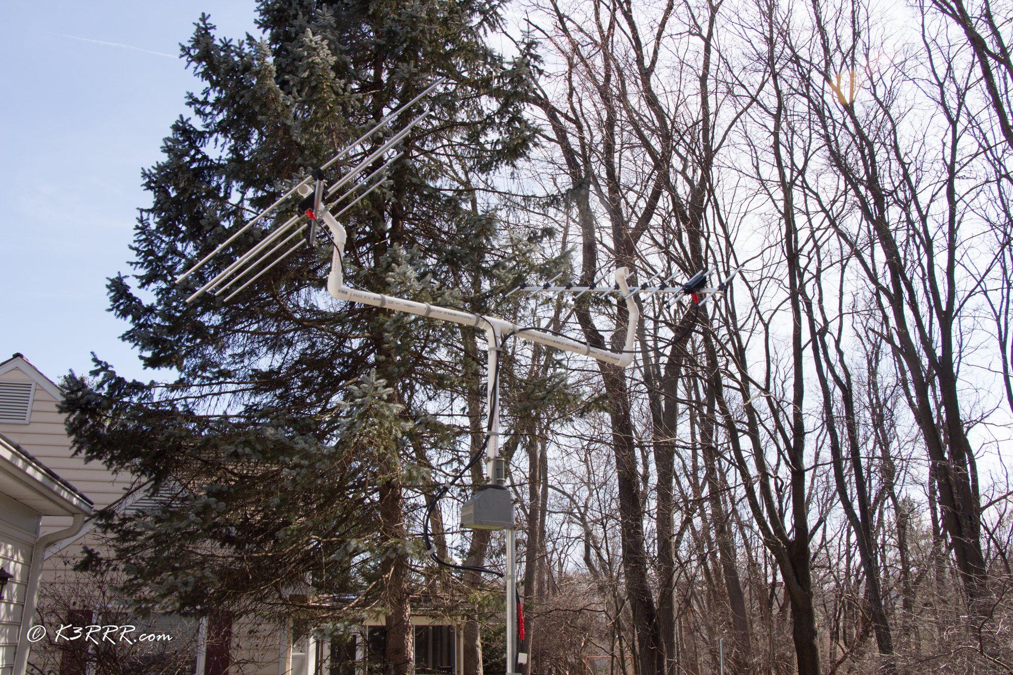
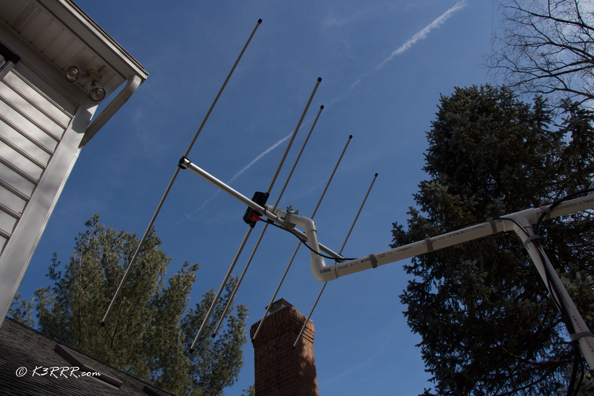
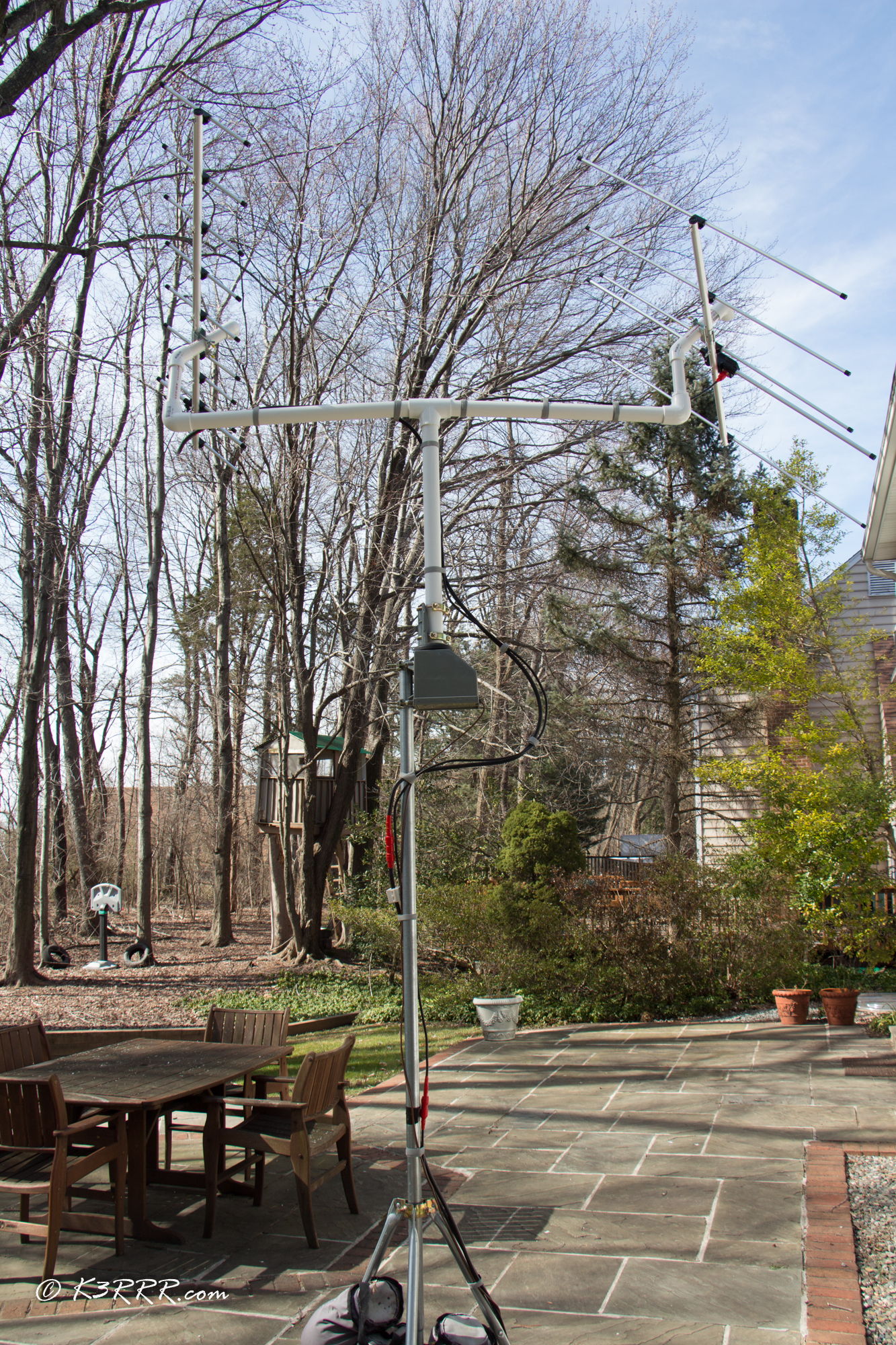
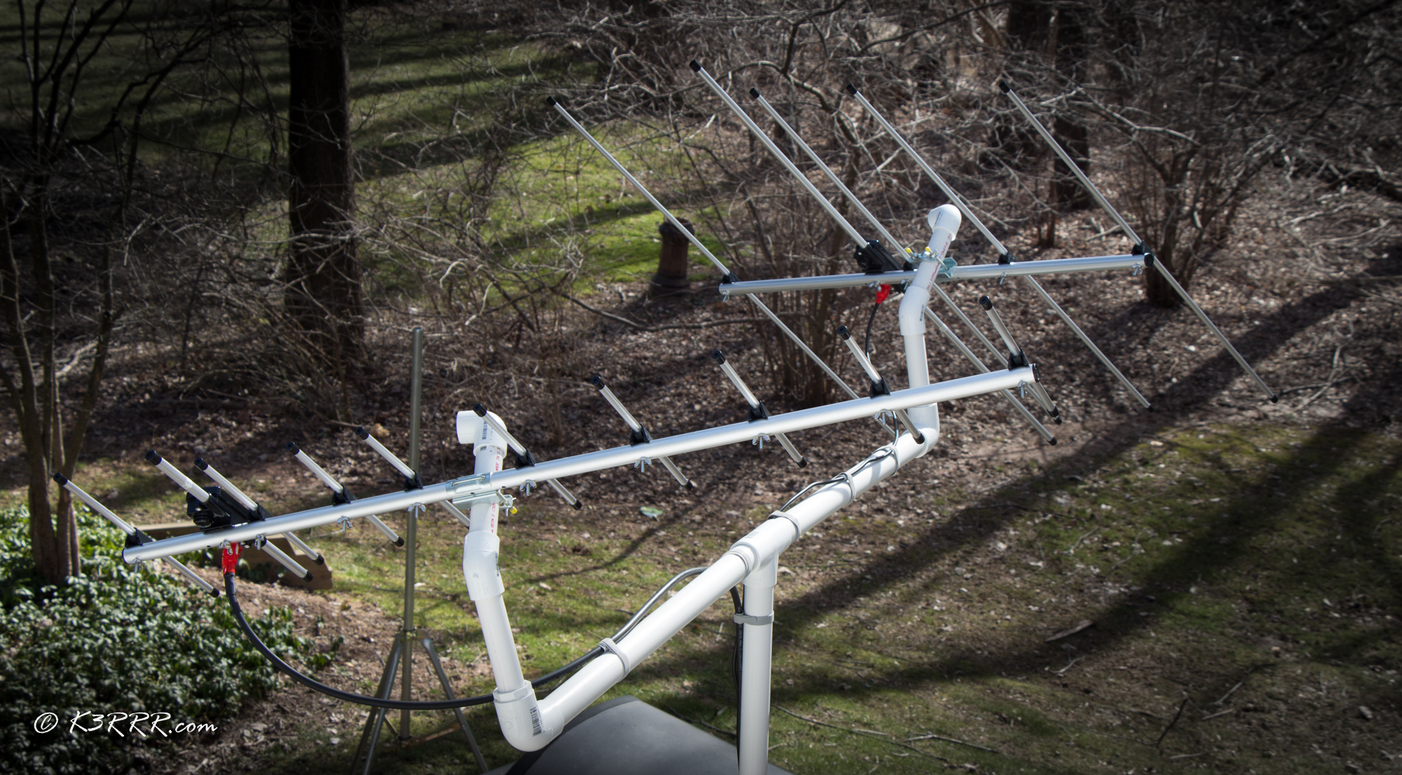
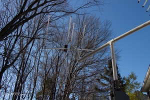
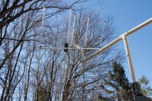
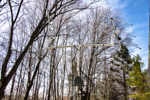
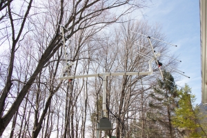
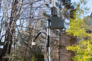
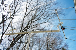
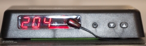
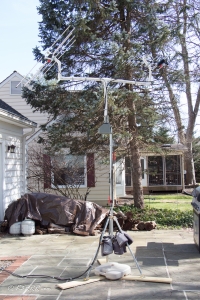
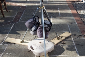
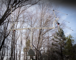
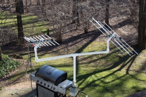
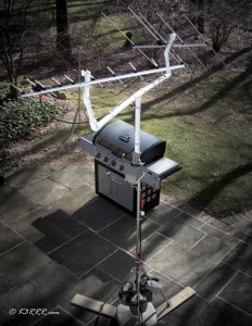
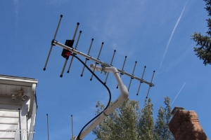
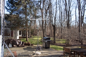
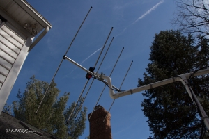
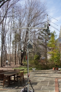
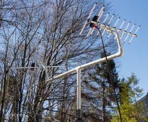
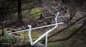
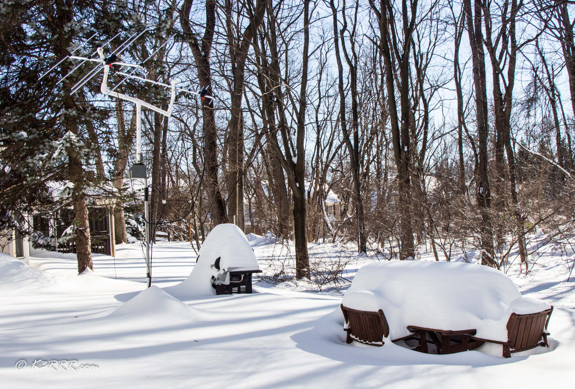
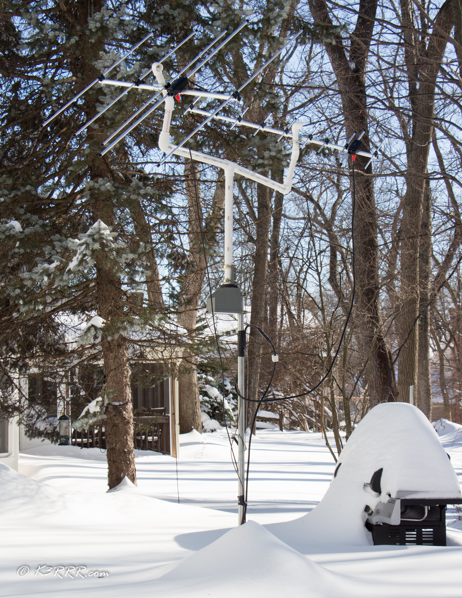
Instead, I’m currently using two small, linear polarized Diamond antennas that have a total cost of $130 ( the A430S10 70 cm 10 element Yagi and the A144S5 two meter five element Yagi), $120 Channel Master 9521A Antenna TV Rotor (see above photo) and about $20 of PVC as you can see in the photo.
(Yes, I know that this rotor is only for azimuth and not for elevation also. As it turns out, if you attach your antennas with a fixed elevation of about 15°, you can work 70% or more of the satellite passes that come your way. “70% of all LEO passes are below 22 degrees.” See the fantastic, detailed PS below written by Bob, WB4APR for details on this.)
“Why Are You Using a 45° Angle for Fixed Elevation Instead of the Recommended 15°?”
I thought I had better add a comment as to why I am obviously using a 45° angle instead of the recommended 15°.
I am personally surrounded by RF eating 65 foot trees and a RF eating two-story house. As a consequence, I chose to move the A430S10 50° antenna beamwidth (see below) and center them on a fixed 45° instead of 15°.
Ostensibly, I would lose coverage from 0° to 20° (45° center angle minus half of the 50° beamwidth of the antennas, or 25° = 20° ) by doing this – but I’m going to lose those angles (and then some) anyway because of the tree and house QRM.
Trust me when I tell you that trees and houses do a damnably good job of blocking RF at satellite frequencies – in my case below 30° in summer and 22° in winter! (This is going to be one of my next videos on my YouTube channel at Youtube.com/K3RRR.)
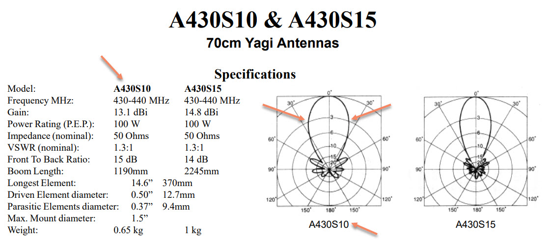
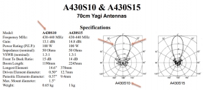
Beamwidth is loosely defined as the width of the main lobe of radiation for both transmit and receive. This is a whole discussion by itself but for my cheapie antenna system, you’re better off with a wide beamwidth versus a more narrow beamwidth for your antennas. The following diagram from Diamond Antennas shows the comparison of what that width of the main lobe looks like with my orange arrows showing where they cross the 3 db points.
If you kinda sorta extrapolate, you can see that an imaginary line from the 3 db intersection point to the outer circle would translate to about 25° either side of the zero mark – for a total spread from both sides equal to about 50° of beamwidth.
(The other chart shows the same info for Diamond’s bigger brother the A430S15 – 15 elements instead of 10. You can see how much narrower the beamwidth is albeit with not that much difference in gain: 1.7 dBi)In more technical terms, the A430S10 has an E-Plane 3 dB Beamwidth = 50 degrees. In layman’s language, this means that you will have a good receive AND transmit signal 25° above and 25° below your center angle – which in my case is 45° due to the constraints of Home Depot.
Home Depot?
I picked 45° because Home Depot sells PVC connectors for that angle – and only that angle since 90° angles really are not that useful for the hamsats!
Again, with these antennas having a 50° beamwidth, my setup handled passes between 20° and 70°. This same wide beamwidth also makes pointing the antenna more forgiving – which is important for cheap rotators which are not all that accurate between calibrations.
(The E-Plane 3 dB Beamwidth = a whopping 95 degrees for the A144S5 two meter five element Yagi – so it was not the limiting consideration.)
But enough about me and why I chose 45°. Let’s talk about you and your need for 15°.
Permanently Bending Schedule 40 PVC With My Wife’s Help
I need to plagiarize myself and steal a couple of paragraphs I have on this other webpage on my site:
“If you have played with PVC for antennas for a while you will already know they don’t make 15° connectors. So, I was faced with trying to bend a straight piece PVC – which I thought was going to be difficult.
“As it turns out, it is surprisingly trivial to heat even Schedule 40 PVC so that it becomes bendable with a standard 1500 watt hair dryer in less than 10 minutes of your time! (Thanks to YouTube for this education!)”
Wife Jan’s hair dryer actually had some attachments and gizmos which focused the heat better than mine so I swiped hers for this task. She was surprisingly unamused and recommended I get a heat gun for future applications. I obediently followed her recommendation and got this particular heat gun.
Something about briar patches came to mind for some reason – even though there was no mention in the Amazon description.
Cheap COMPUTER Control for Your CHEAP Rotator
Note: The following approach will NOT work with just any infrared controlled rotator. It works with the Channel Master 9521A Antenna TV Rotor and probably all similar Channel Master IR rotators like the updated version Channel Master CM-9521HD. It might work with others but it does NOT work with the super cheap RCA type rotators.
Note this also works well for non-satellite computer controlled rotor applications like TV rotators for HF spider antennas, other small antennas like VHF/UHF beams, etc.
The nice thing about this particular rotor is that it is infrared controlled. Infrared is nice but the question is how to computer control this rotor?
Cheap Computer Control of My Cheap TV Antenna Rotor – PstRotator and the USB-UIRT
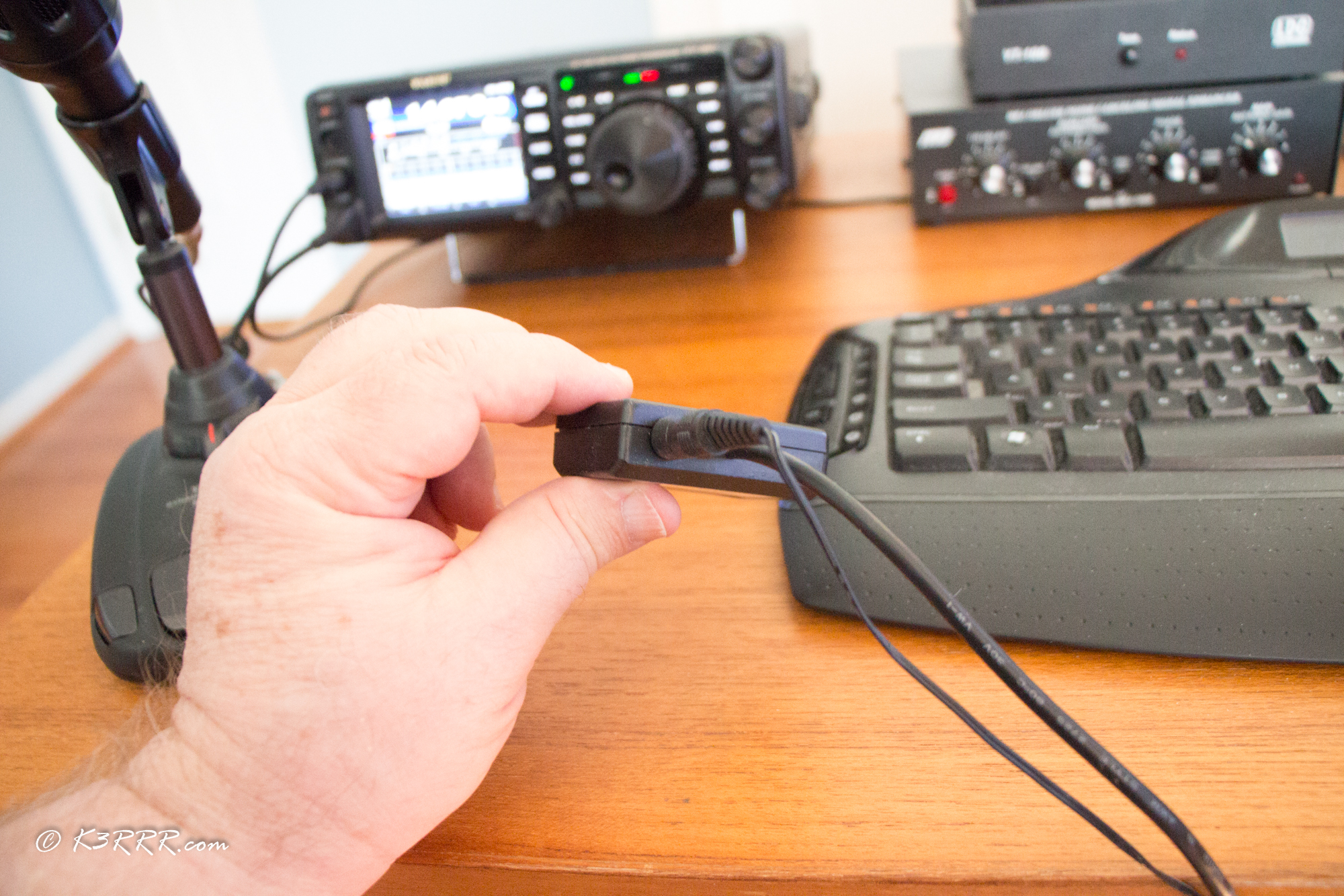
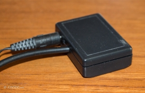
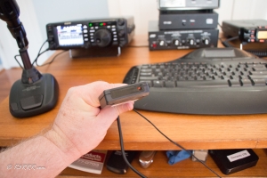
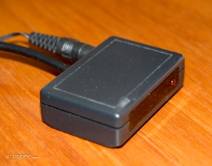
Friend Robin recommended that I check out a program called PstRotator. I chatted with the developer, Codrut YO3DMU, in Romania and he said all I needed was his software and the magic hardware that made all this work: the Jon Rhees USB-UIRT USB Universal Infrared Receiver and Transmitter that cost me about $65 delivered.
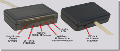
One nice thing about the USB – UIRT is that it allows for an external IR emitter. As it turns out, I happen to have one of these left over from an old Windows Media Center remote that worked fine for this application after I attached it with a little rubber cement to the Channel Master 9521A Antenna TV Rotor control.
I highly recommend you get one of these for under $7 so you don’t have to keep the front of the UIRT directly in front of the rotator controller. Here’s one that looks right from Amazon: IR Infrared Emitter Extender Cable Extension (10 Feet 3M.)
Although I have not yet tried this particular one, I fully expect it should work. (Great thing about Amazon: If it doesn’t work, you can return it.)
The great thing is that the USB – UIRT is totally plug-and-play once you download the drivers from the USB – UIRT website. There is no programming or software involved with the gizmo.

Add to this the €20 (about $21) for Codrut’s PstRotator software and the combination of this hardware and this software was as close to plug-and-play as I’ve seen in a while.
On top of this, as it turns out, PstRotator also includes its own Satellite Tracking Module for no extra charge!
For setup, you will need to go to the set up procedure with PstRotator once you download the software.
(Codrut also offers a second program that is included in the same license called PstRotatorAZ that is intended just for azimuth rotors. I did make the mistake of assuming that that was the right one for me since I only have an azimuth rotor. That was wrong. Because we want to track satellites, you need to choose the non-azimuth version called simply PstRotator.)
For set up: Choose Setup/AZ Controller and then choose USB-UIRT Channel Master at the bottom of the list.
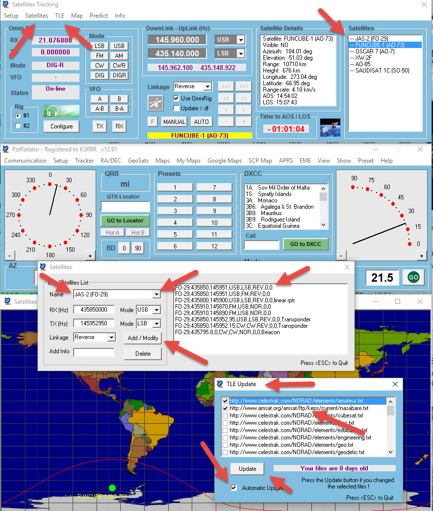
If you want to use the built in Satellite Tracking software, use the drop down menu Tracker and then select Satellites at the top of the list right below Sun. That will bring up the Satellite Tracking software shown below:
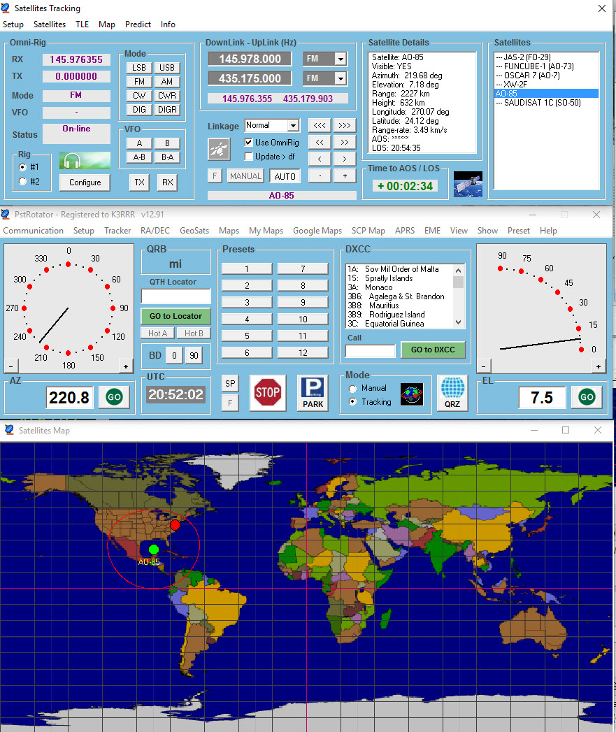
To set up the Satellite tracking module, click on TLE and choose your dataset such as amsat.org then go to the drop down menu Name to choose a satellite such as Jas-2 (FO-29)….then highlight which setting you want for each satellite:
(e.g. FO29:435850,145951,USB,LSB,Rev,0,0) ….
then click add/modify (this step is easy to miss.) Once you have done this, then the satellite shows up on the main Satellite Tracking display on the right.
Oh, one other thing: If you have no other software for rig control such as Ham Radio Deluxe, the install subdirectory that comes with PstRotator includes Omni Rig which is pretty trivial to set up.
That’s all there is to it! PstRotator with the USB – UIRT interface makes a great combo for cheaply and easily getting on the birds.
Conversely, I have been struggling for months to try to get the Satellite Tracking Module of the paid version of Ham Radio Deluxe to work right – especially with the linear birds since the manual tuning for HRD does not operate correctly. (It still doesn’t – although I understand they are finally starting to address the Satellite Tracking Module with some increased priority.)
Likewise, I’ve used SatPC32 which is directly linked with AMSAT. It’s a good program but I find it overly complex and I don’t believe that it’s been substantively updated since 2013 – which means that it does not include support for many newer rigs.
PstRotator – Highly Recommended for Your Satellite Tracking Needs
Instead, I find that PstRotator just works. No hassles, no complexities and it seems to work equally well with the linear birds as well as the FM birds. It is now easy for me to work the satellites with a single radio – my Yaesu FT 991.
Note: I eventually added a second FT-991 for full duplex operation which is GREATLY preferred. However, a cheaper approach for full dux is to add a non-dongle SDR like my SDRplay – and use that for the receive side to have full duplex operation!
Check out my YouTube Channel, YouTube.com/K3RRR, for videos on a lot of this stuff – including getting PstRotator and SDRuno software working for doppler control of your SDRplay!
I really wish that the Satellite Tracking Module of Ham Radio Deluxe worked just like the Satellite Module for PstRotator.
I still greatly prefer the original graphics of Simon Brown for Ham Radio Deluxe over the graphics in PstRotator. However, substance over form wins out and PstRotator is my current go to program for working the amateur satellites.
Hopefully, someday soon, the HRD folks will be able to at least mimic Codrut’s great satellite tracking software. Even if and when they do, I’ll continue to use PstRotator as my rotor control software.
Irrespectively, PstRotator with the USB – UIRT interface already works now and works right.
With at least a 18 current, popular ham radio satellites circling the earth that you can work and with at least two more scheduled to be launched in 2018, this is a great time for you to finally get active on the satellites!
73,

Robert
K3RRR
PS: Check out my YouTube Channel, YouTube.com/K3RRR, for videos on a lot of this stuff.
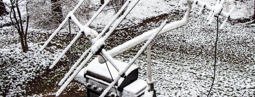
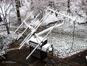
PPS: The photos with the snow are from what we Washingtonians call “Snowzilla” which dumped 3 feet of snow at our QTH during January 2016.
PPPS: Be forewarned, when it comes to working the ham radio satellites, I sometimes feel like the quote from Apollo 13: “Jim Lovell: All right, there’s a thousand things that have to happen in order. We are on number eight. You’re talking about number six hundred and ninety-two.”
I have been playing with the satellites for decades – and I am now up to number ten.
PPPPS: With regard to only have an azimuth rotator, here is a great analysis by one of my favorite ham radio gurus, Bob, WB4APR
[amsat-bb] Re: Satellite Average Elevation & New Birds
Robert Bruninga bruninga at usna.edu
Wed Dec 18 06:16:56 PST 2013
The geometry of LEO satellites has not changed. The optimum angle for a fixed tilt modest gain YAGI is about 15 degrees (assuming you have a decent horizon).
See: http://aprs.org/LEO-tracking.html
That said, if your antenna is seriously blocked from all directions below say 10 degrees, then you are not going to hear anything down there anyway. So bump it up to say 20 or 25. But 70% of all LEO passes are below 22 degrees so just recognize that you are giving up most of your operations.
Bob, Wb4aPR
—–Original Message—–
From: amsat-bb-bounces at amsat.org [mailto:amsat-bb-bounces at amsat.org] On
Behalf Of Clayton Coleman
Sent: Tuesday, December 17, 2013 8:35 PM
To: Ted
Cc: AMSAT-BB
Subject: [amsat-bb] Re: satellite average elevation & new birds
Just a short time ago after I moved into a new shack, I operated for a month with an Elk at 15 degrees on a tripod. Armstrong rotor. I worked all the current satellites right up through the first week we had AO-73’s transponder available.
Pay close attention to comments WB4APR has made about setting the fixed elevation based on the lowest horizon you can work. For example, if it takes ten degrees for you to clear a mountain, twenty five degrees is probably okay. If you have a clear horizon view, fifteen is probably okay. The goal is to have as much gain available at your lowest elevation to increase your available range. YMMV
PS A preamp goes a long way in a fixed elevation setup.
73
Clayton
W5PFG
On Dec 17, 2013 7:24 PM, “Ted” <k7trkradio at charter.net> wrote:
> I’m kind of looking for an update from Bob, but can’t find his email right now…
>
> But the question is, in view of what appears to be some renewed interest in working the new cubesats, et al, is asking Bob to comment on his earlier thoughts on using antennae at fixed elevations. For me, I’m using my Elk on a Rat Shack rotor at a fixed el per Bob’s recommendations. (I’m still struggling with PCSAT32…!!!%^&*!!) but, this antenna set up is very cost effective and seems to perform pretty well.
>
> For example, Joel Black has asked for some advice in an earlier posting. My concern is that new operators or those returning run out and spend a bunch of $$$ on a new setup. No one knows how long the current crop will last or if a new crop is in the future, so probably some caution on the Visa is warranted.
>
> Just asking (and especially Bob)
>
> 73, Ted
> K7TRK
>
>
> —–Original Message—–
> From: amsat-bb-bounces at AMSAT.Org [mailto:amsat-bb-bounces at AMSAT.Org]
> On Behalf Of Bob Bruninga
> Sent: Tuesday, April 12, 2011 8:23 AM
> To: amsat-bb at AMSAT.Org
> Subject: [amsat-bb] Re: satellite average elevation
>
> > we used a horizontally polarized yagi fixed at 30 degrees above the horizon. That worked very well..
>
> Thanks for the confirmation. Yes, elevation rotation is simply not needed at all for LEO spacecraft and modest beams. A mild, fixed tilt modest beam is just perfect.
>
> But, the “30 degree” angle myth is very pervasive throughout amsat, whereas, the optimum angle is more like 15 degrees.
>
> A 30 degree up-tilt gives up too much gain (-3 dB!) on the horizon where signals are weakest and where satellites spend most of their time, and puts the gain in an area of the sky where the satellite is already 6 dB stronger and is rarely there (giving you max beam gain where you need it least).
>
> If you look at the sketches on the web page, the optimum angle is more like 15 degrees up-tilt. It preserves max gain on the horizon within 1 dB (where it is needed most) and focuses the breadth of its gain on the area of the sky where the satellites spend something like 95% of their time. For the missing 5%, the satellite is right on top of you and almost 10 dB stronger without any beam at all. Oh, and the 15 degree up-tilt beam is also perfect for Terrestrial operations as well.
>
> See the sketch on: http://aprs.org/rotator1.html
>
> In some future life, if we ever get back to HEO’s and huge OSCAR arrays, then elevation rotors have a place. These high-gain beams have such narrow gain patterns, that higher precision tracking is a must. (Though it is complete overkill for LEO’s).
>
> Using these OVERKILL arrays for LEO’s adds significant complexity to LEO operation requiring higher precision tracking, elevation rotors, better timing, fresher element sets and automated operation.
>
> Using a TV rotator and 15 degree fixed tilt beam is much more forgiving…
>
> Bob, Wb4APR
>
Hi there,
I absolutely love the website and YouTube feed! What a great wealth of information.
I do a lot of FM DX’ing and have long owned the USB-UIRT cable and use PstRotator, as you said, such a cost effective way for a total remote rotator solution!
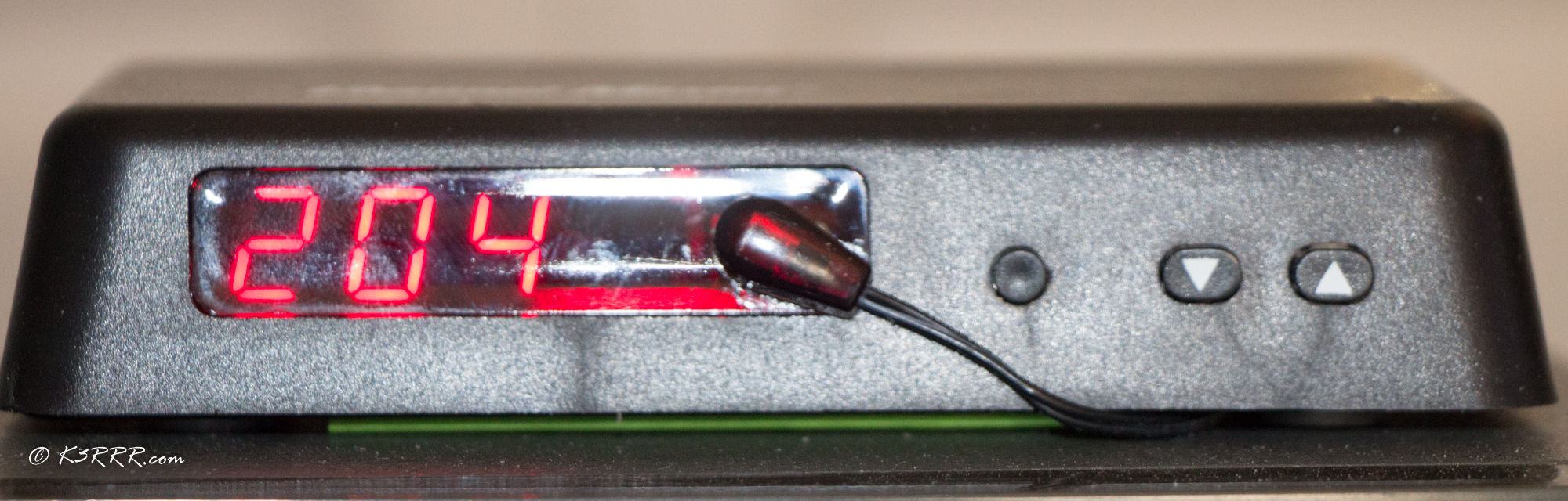
I have the same digital ChannelMaster control box as shown in your example. For the life of me, though, I’ve never been able to get PstRotator (or PstRotatorAz) to show me what azimuth the control box is currently situated at (i.e. receive data). I can send without any issue and turn the control box all day long. But if, for example, I physically changed the azimuth of the control box, I’d have no way of knowing where I’m starting from with just PstRotator.
It looks like from your video and documentation that you are able to pull the current position, am I correct? If so, was there anything special you had to do to make that happen?
This is exactly what I am looking for – not for satellites – just for a remote stations ChannelMaster rotor. Since the remote station is using a RPi, do you know if any linux software that world work with the box for simple rotator control?
Got this great email from Ted, K7TRK and, with his permission, I am including it here for additional ideas and thoughts for the readers.
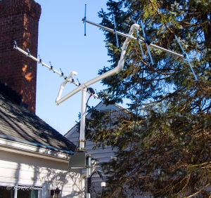
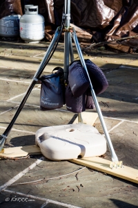
Hi Robert, just saw your note on the ‘angle’ issue. Pls see my pictures and the attached email from a while ago. The metal fence adjustable bracket (rail end cap in Home Depot speak) takes the pvc and is fully adjustable.
Hope this helps
73, Ted
K7TRK
Ok, here goes. All parts from Home Depot but Lowe’s will have the same parts.
The green colored pipe: 1″ schedule 40 pvc
Inside of the pvc pieces is a wooden dowel (a tight fit). Look in the lumber dept. This may be overkill but I think it adds strength, especially for the piece that goes in rotor. When the pvc starts to degrade, there will still be some structural integrity. The length of the pieces is arbitrary. I thought putting the mass of the antenna right over the rotor made sense for balance.
The adjustable joint is a part found in the chain link fence dept. It is called a ‘rail end cap’. As you can see or envision, 2 of them will go side to side with a bolt large enough to fill the hole and a lock or star washer and nut. Fully adjustable. There may be a better way to create this joint, but this is simple and strong and easily adjustable.
The rail end cap is just a bit larger than the pvc so you will need to run a bolt through as shown. Gorilla glue was placed in the end of the cap.
The pvc piece that joins at the Elk’s ‘tee’ was not glued but a bolt and nut drilled through. A press fit so other connections to the ‘tee’ can be made if needed.
Paint the pvc to protect from the sun.
You have probably seen the discussion about fixed elevation (15 vs. 30 degrees) so I’m not going there. I am at about 25 degrees for now. I need to clear some hills and the roof ridge so that’s where I am. The antenna is on the back deck and the lot slopes to the rear. It’s about 25 feet agl net.
I can now hit AO51 at +- 9-10 degrees when it is still over San Diego/Baja Calif., so it is much better than moxie. I can be full quieting. When you have a direct overhead pass, there is a little null when it is directly over head, but the rest of the pass makes up for it. The other day, I contacted N Carolina on a lower eastern pass, so coast to coast is possible !!
I have not yet tried SSB or linear bird but this setup makes me question even the need for the full az/el rotor deal, at least for now. My preamp is in the shack and will stay there.
I agree on the Arrow. Seems like too much metal to put up on the rotor. The Elk is pretty compact.
73, Ted
Got this great email from Jerry, K5OE and, with his permission, I am including it here for additional ideas and thoughts for the readers.
Robert,
Nice piece of work! Thanks for sharing all of it in such great (and easy to replicate) detail. I just wanted to add some comments on (the debate about) antenna pointing angle for LEOs… based on many (too many?) years of chasing states, countries, grids, etc.: it may all depend on your own particular situation AND goals (i.e., there is no one magic formula/solution/design for everyone).
The single biggest factor (after getting past HOAs, partner objections, and fear of heights) is: can you see the horizon unobstructed by building and foliage? If trees are a problem, are they deciduous… so possibly not an issue in winter? If you do have blockage, Bob’s (WB4APR) recommendation of pointing the antennas at 15 degrees above the blockage is pragmatic and well proven. Read no further.
If, however, you are lucky enough to see the horizon, you might consider pointing your antennas directly at it. This gives you maximum gain from the antenna AND maximum ground gain (you will know it when you hear it, typically under 5 degrees) when the satellite is the farthest from you, giving you brief access to the farthest/hardest/most rare states, countries, and grids. I can’t count the number of rare grids I have snagged at -1 and -2 degrees (yes, negative, over-the-horizon) just as the downlink faded! The null you may/will experience directly overhead is very brief and only on passes typically above 75 degrees. Those contacts are the easy ones anyway.
One final word: if you have worked everyone within near-LEO range and you ONLY want those at your horizon, orient (regardless of pointing angle) your antennas at horizontal (flat) to maximize your ground gain potential. There is practically no ground gain on vertical polarization, and you lose half if you orient your antenna at 45 degrees. You will only hear below-the-horizon signals with horizontal polarization.
73,
Jerry, K5OE
Satellite WAS/DXCC/VUCC 1,000