I am personally fascinated by the cheap $25 RTL–SDR dongles that are available on Amazon and eBay. I’ve already got three of them along with one Ham-It-Up upconverter that I use for HF.
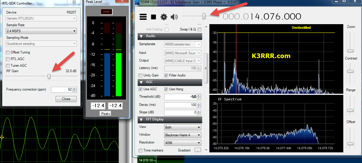
For the one that I use on HF, I have found that setting the audio level correctly for maximum decodes on digital signals is sometimes difficult since you have both a controller configuration RF gain setting – AND a volume control in SDR#, HDSDR, SDR–Radio.com V2, – or whatever other SDR software that you’re using.
If you enjoy digital modes with your SDR – software defined radio – like I do, you might want to download two great tools that will help you make sure that your settings are correct for maximizing the decodes or just improving the audio from your SDR.
These tools are Peak Level Meter and Soundcard Oscilloscope. There’s also a link to VB–Audio cable which I use with my RTL SDR.
Peak Level Meter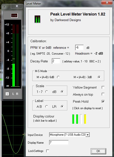
If you look in the above picture and the one to the right, you can see that one of the programs in the screen grab is Peak Level Meter.
This is a terrific, very small, very low overhead program that I have constantly running on my ham radio computer. It lets me adjust the signal level on both of my SignaLinks and my virtual audio cable by VB–Audio Software which I use with my RTL SDR.
(VB-CABLE driver will be present as new playback and recording device (appearing in the audio device list). VB-CABLE can be set as default device, as any regular audio device. The Configure and Properties buttons allow to setup multi channel features and device sound quality. All signal coming in the CABLE input is going to the CABLE output. Then It becomes simple to make computer audio recordings or to connect the received audio from your SDR to a digital application such as PSK31.)
The screen grab to the right shows both the Peak Audio Meter and the right-click options that are available with the Peak Audio Meter.
Here’s the bottom line: setting your level properly with the peak level meter: increase your volume until it is showing approximately -8 db max on the meter.
This will make sure that you have enough headroom and that you will not overdrive the audio into your various applications such as DM-780, JT-65, WSJT etc.
Here’s the link to the free software…
http://www.darkwooddesigns.co.uk/pc2/meters.html#Quad
Main features:
- Fallback ballistics are accurately modeled but the attack time (eg the BBC spec of 2.5dB down for a 10ms burst) is not. Peaks as short as 1ms register accurately. The fallback time from 1 to 7 is now in line with BBC specifications, 2.5 to 3 seconds. You may prefer a faster fallback, especially as there are the peak markers, so the fallback time can be adjusted by means of an arbitrary value entered on the options page. A value of 2 corresponds to the BBC PPM spec. Values up to 10 speed up the decay.
- Mono matrix can be set to M = (A+B) –
3dB or 6dB. Traditionally the BBC have used M3, though M6 is increasingly used. Channels can be labelled L & R or A & B.Displays Left, Right, Mono (sum) and Stereo (difference) simultaneously. - The peak markers can be set to hold the peak. Click on the window to reset.
- There is also a 20dB button. This increases the gain of of the Stereo difference indication by 20dB (10 times). M, L & R are not affected.
- The colour of each bar can be set to any colour from the options screen. By default all bars are green but it possible to have, for example, red and green for A and B.
- Clicking on the small button bottom-
left closes the Mono & Stereo display for those where only Left & Right is wanted.The settings can be locked. - Tick the ‘Lock Settings’ box and enter a password which will allow un-
locking. To unlock, click the ‘Lock Settings’ box and enter the password. This is not high security and is only intended to prevent accidental changes. The lock can be removed by deleting the .ini file. - Requirements: A soundcard capable of 44.1KHz 16 bit stereo sampling is required. For Windows XP, Vista, 7 or 8 – Vista, 7 or 8 recommended. Note: ASIO drivers are not supported.
It is possible to have dozens of instances of the Level Meter running simultaneously if one was mad enough. The processor load is very small.
Soundcard Oscilloscope Software
This free Soundcard Oscilloscope software lets you monitor your digital audio microphone settings on your USB soundcard to make sure you don’t see any square wave – if you see square waves, it means you are distorting your input to DM-780, JT-65, WSJT etc.
I use this Soundcard Oscilloscope software along with the peak meter shown above to make absolutely certain that I am not flat topping on any of my digital signals. (I have gotten almost fanatical about this!)

The screen shot is referencing the same kind of issues using a SignaLink or other USB device – but the same applies to using a virtual audio cable with your SDR: keep the levels low enough to not flat top!
Here’s the link to the free software…
http://www.zeitnitz.eu/scope_en
If his site is down, you can download it directly from my server: https://k3rrr.com/scope_146.zip
Any other suggestions for how you can use this scope? Please post them in the comments!

(The screen grab is my mic input signal into one of my SignaLink USBs showing I am not overdriving my input into DM780.)
Main features:
The PC based Soundcard Oscilloscope receives its data from the Soundcard with 44.1kHz and 16 Bit resolution. The data source can be selected in the Windows mixer (Microphone, Line-In or Wave). The frequency range depends on the sound card, but 20-20000Hz should be possible with all modern cards. The low frequency end is limited by the AC coupling of the line-in signal. Be aware, that most microphone inputs are only mono.
The oscilloscope contains in addition a signal generator for 2 channels for sine, square, triangular, sawtooth wave forms and different noise spectra in the frequency range from 0 to 20kHz. The signal can be defined by a mathematical formula as well. The signals are available at the speaker output of the sound card. These can be fed back to the oscilloscope in order to generate Lissajous figures in the x-y mode.
Additional features:
- Lissajous figure generated and displayed by the soundcard oscilloscopes (x-y mode)
- Trigger modes: off, automatic, normal and single shot
- Trigger level can be set with the mouse
- The signals of the two channels can be added, subtracted and multiplied
x-y mode - Frequency analysis (Fourier spectrum)
- Waterfall diagram (frequency spectrum as function of time)
- Frequency filter: low-, high-, band-pass and band-stop
- Cursors to measure amplitude, time and frequency in the main window
Audio Recorder to save data to a wave file - For multi soundcard system, the used card can be selected in the settings tab
When in Doubt Use Both!
As I said above, I use both of these great tools simultaneously for both of my SignaLinks and also for my RTL SDR.
The below screen grab shows my desktop on my ham radio computer while I’m working JT-65 and PSK-31. Note that I’m using both the Peak Meter and the Soundcard Oscilloscope software to make sure I’m driving my audio levels correctly.
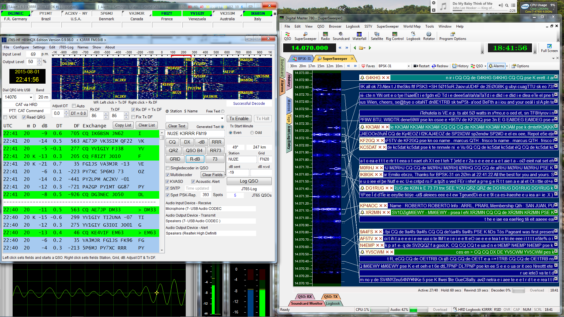 There is a ton of additional software applications that require digital signal reception from your SDR. All of that can also greatly benefit from these two tools!
73 / 72,

K3RRR
-.- …– .-. .-. .-.
73 de Robert K3RRR
http://K3RRR.com
@K3TripleR
http://YouTube.com/user/K3RRR
-.- …– .-. .-. .-.
Leave a Reply
Want to join the discussion?Feel free to contribute!