Check out these ARRL images:
FD 2016 081
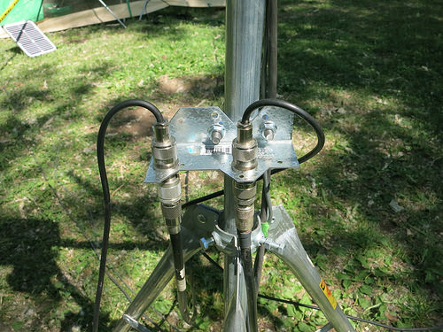
Image by ve2ddz
Image from page 513 of “QST” (1915)
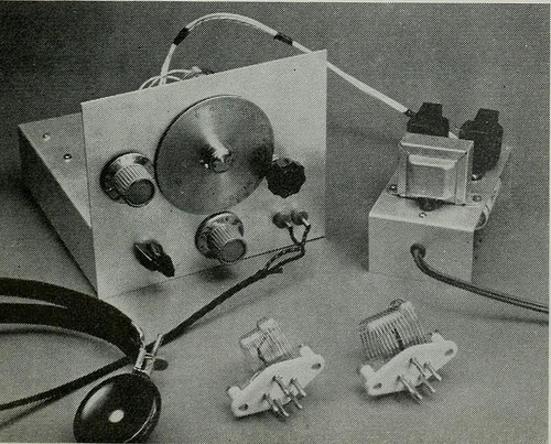
Image by Internet Archive Book Images
Identifier: qstamer00amer
Title: QST
Year: 1915 (1910s)
Authors: American Radio Relay League
Subjects: Radio Radio
Publisher: [Newington, Conn., etc., American Radio Relay League]
Contributing Library: Internet Archive
Digitizing Sponsor: Internet Archive
View Book Page: Book Viewer
About This Book: Catalog Entry
View All Images: All Images From Book
Click here to view book online to see this illustration in context in a browseable online version of this book.
Text Appearing Before Image:
least at the beginning. This article describes the construction of asimple one-tube regenerative receiver that willfulfill the basic requirements for communicationswork. The title of the article states that thereceiver is a one-tube job. Actually, it uses twotubes in one envelope — envelope meaning theglass enclosure. The 6U8 is a triode-pentode, andin this receiver the pentode section is used as aregenerative detector and the triode portion asan audio amplifier. With this receiver it is possible to hear amateurand commercial stations in the 2- to 20-Mc.range. This tuning range will enable the builderto listen to the two low-frequency Novice bands.Also, if one is interested in obtaining codepractice, WlAW, the ARRL Hq. station, can betuned in for its nightly code-practice sessions. The Circuit The circuit used in this receiver differs in a fewplaces from the usual regenerative-receiver cir-cuit. For example, instead of the usual smallantenna-coupling capacitor or inductor, provision
Text Appearing After Image:
was included here for either a series- or parallel-tuned antenna circuit. This allows a wide rangeof coupling adjustments to be obtained, as isoften necessary with regenerative receivers. Referring to Fig. 1, the antenna coil, Li,couples the signal to the detector tuned circuitL2C2C3. The capacitor, C2, is larger than C3 andis used as the handset capacitor — once Czis set for a particular frequency range, C3 is usedas the bandspread tuning control. To facilitateusing manufactured coils, the coil L2 is tappedto obtain a feed-back or tickler winding. Re-generation in the detector is controlled bychanging the screen voltage obtained at thepotentiometer Ri. An r.f. filter, using two cap-acitors and an r.f. choke, is placed in the platecircuit of the pentode detector to reduce r.f.appearing at the grid of the triode audio ampli-fier. Still further attenuation of r.f. at the gridis obtained through the use of a series resistorand a shunt capacitor right at the grid of theaudio stage. To s
Note About Images
Please note that these images are extracted from scanned page images that may have been digitally enhanced for readability – coloration and appearance of these illustrations may not perfectly resemble the original work.




Leave a Reply
Want to join the discussion?Feel free to contribute!