Check out these Standing Wave Ratio images:
G0FAH Dipole SWR Frequency Plot
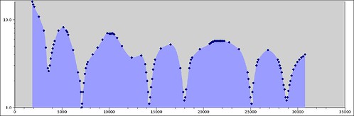
Image by OpalMirror
This is the standing wave ratio (SWR) plot for my G0FAH style antenna (from the ARRL Classic Wire Antennas volume 2 article ‘5 Bands No Tuner’). I measured it using an MFJ-259B Antenna Analyzer I borrowed from a friend, which saved a lot of time in sampling all the data. Yes, I spun a knob and captured each datum plotted by hand.
For the less technical, here’s what’s happening. A transmitter shoves power (measured in Watts) into a transmission line to the antenna. This is called ‘forward power’. Some power eventually gets to the antenna and radiates into space (this is ‘radiated power’). Some of the power bounces back at the transmitter (‘reverse power’). Finally some of it heats up the transmission line (‘heat’). Power bouncing back is not only harmful to the transmitter (high voltages, mostly), it also results in more heating in the transmission line as the waves reflect back and forth (that’s bad). An ideal SWR is 1:1, and anything over 2:1 is increasingly bad news (the vertical axis on the plot shows the first SWR number, basically the higher the more reverse power, so ‘low points’ are good!).
How to reduce SWR? SWR depends in part on antenna and transmission line materials (copper wire, plastic window material, coaxial cable, insulators). More importantly, adjusting antenna and transmission line geometry (length, layout) affects the SWR. You can tweak the lengths until the low SWR spots match up with the frequencies that you care about.
Finally, an antenna tuner is a box with adjustable coils and capacitors inline and shunted to ground, and this helps match an antenna with too much capacitance or inductance so it doesn’t present high voltages and currents to the transmitter itself… the line heats up still but the transmitter doesn’t get cooked.
SWR Frequency Plot – Diamond X-30A
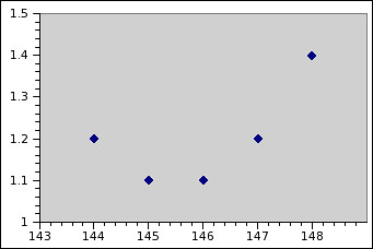
Image by OpalMirror
This is a Standing Wave Ratio plot vs. frequency for a Diamond X-30A VHF/UHF dualband antenna that I have 35′ off the ground at my home operating location, tested with an MFJ-259B. Not surprisingly, it looks just like the specifications.
I’m already using this antenna frequently for local simplex nets (a net is an on-the-radio meeting), one-on-one chats with hams on the go, the South Clackamas County ARES group, the Molalla Amateur Radio Club, as well as talking to hams through any one of the couple dozen local repeaters (local is anything from Salem to Portland to Mt. Hood). It works *much* better than a magmount on the metal roof of the house!
Miracle Antenna w/counterpoise clip
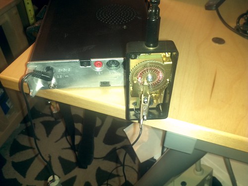
Image by wwward0
I’ve had very little success tuning the Miracle Antenna for 70cm (Ham UHF) operation. The FT-817 complains about high SWR regardless of my efforts to adjust the length for 3/4th wave. However, after clipping a short lead to the shield I’ve been able to get it into "safe" territory with regard to SWR – at least, under the radio’s threshold for the SWR alert. I don’t know what the panel meter is calibrated against, but out of its full range, it’s 4 bars on FM at 5 watts and 3 bars at the lowest power rating. I think there are 8 bars total. Anyway, it’s very touchy.
I left my rubber duck antenna at Resistor and probably won’t have it in hand for a few days, so I was especially interested to get this up and running. The product is sold as UHF friendly, with reasonable performance on UHF (< 2:1 standing wave ratio) so I suspect there is a bit more study required to tune it but otherwise it’s possible to do so.
In the meantime, while it offends my sensibility to do so, I’ll leave the back cover off and use this counterpoise. The rear radio panel has a lug for grounding, but clipping the counterpoise to this or the shield does not help the tuning (or moves it further out in length than I’ve been checking.)
Note that with this tuner, the antenna detent for VHF is very important – it’s the pass-through circuit on the rotor, and is followed by a couple detents which place the wiper over a nonconductive area.
When time permits (and it’s going to be awhile) I’ll work out something more sensible.
KD4ISF

