Image from page 146 of “QST” (1915)
Image by Internet Archive Book Images
Identifier: qstamer00amer
Title: QST
Year: 1915 (1910s)
Authors: American Radio Relay League
Subjects: Radio Radio
Publisher: [Newington, Conn., etc., American Radio Relay League]
Contributing Library: Internet Archive
Digitizing Sponsor: Internet Archive
View Book Page: Book Viewer
About This Book: Catalog Entry
View All Images: All Images From Book
Click here to view book online to see this illustration in context in a browseable online version of this book.
Text Appearing Before Image:
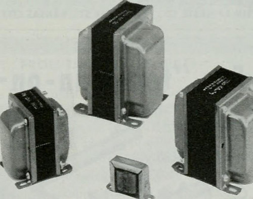
Me^jU FREED COMPONENTS /o^ HI-FIDELITY AMPLIFIERPROVIDE IMPROVED PERFORMANCE This Freed circuit incorporates several changesfrom the original Williamson circuit to provide op-timum performance at high and low frequency ex-tremes. It is rated at 10 watts with triode connectedoutput tubes. However, by connecting the screengrids of these tubes to taps provided on the FreedKA-10 output transformer, it is possible to doublethe power output for a given distortion percentage. Recommended power supply is choke-input typewith a two-section L-C filter to maintain constantD.C. output and to improve filtering to the voltageamplifiers. Other high quality Freed components Include minia-ture audio transformers, magnetic amplifiers, toroidalinductors, subminiature encapsulated pulse trans-formers, precision filters and a complete line ofprecision laboratory test instruments. Complete cata-logs are available to engineers requesting same onfirm letterheads.
Text Appearing After Image:
Freed components requiredfor this amplifier include:FREED KP-IO POWER TRANSFORMERFREED KA-IO OUTPUT TRANSFORMERFREED KC-10 FILTER REACTORFREED KC-n FILTER REACTOR A DETAILED TECHNICAL SHEET AND PARTS LIST IS AVAILABLE ON REQUEST ASK FOR BULLETIN NO. 5402 FREED TBANSFOBMER CO.. INC. 1703Weirfield St..Brooklyn (Ridgewood) 27, N.Y. 141 Be^^ of Your Transmitter to Antenna Matchwith the new CoAx Ratiometer (swr.) Install a CoAx Ratiometer in the line between your trans-mitter and antenna (or tuner) and stop guessing at a propermatch. In this new device, well-established principles areapplied to produce a unique answer to the problem ofmeasuring standing wave ratios. The result is a design ofexceptional accuracy and simplicity. There are no condensors to balance, no resistors in lineto dissipate your power. The unit handles frequencies from2 to 200 MCS, power loads from 10 to 1000 watts (so itcant be overloaded). Rugged construction, but so compactit can easily be permanently installed insi
Note About Images
Please note that these images are extracted from scanned page images that may have been digitally enhanced for readability – coloration and appearance of these illustrations may not perfectly resemble the original work.


Leave a Reply
Want to join the discussion?Feel free to contribute!